High velocity low pressure emitter

a low-pressure, emitter technology, applied in the direction of burners, combustion types, combustion processes, etc., can solve the problems of insufficient volume of flow from the resonance tube, low velocities of particles generated by the atomization process, and inability to meet the requirements of fire protection applications

Active Publication Date: 2006-12-14
VICTAULIC
View PDF45 Cites 34 Cited by
  • Summary
  • Abstract
  • Description
  • Claims
  • Application Information

AI Technical Summary

Problems solved by technology

Resonance tubes of known design and operational mode generally do not have the fluid flow characteristics required to be effective in fire protection applications.
The volume of flow from the resonance tube tends to be inadequate, and the water particles generated by the atomization process have relatively low velocities.
As a result, these water particles are decelerated significantly within about 8 to 16 inches of the sprinkler head and cannot overcome the plume of rising combustion gas generated by a fire.
Thus, the water...

Method used


Image

  • High velocity low pressure emitter
  • High velocity low pressure emitter
  • High velocity low pressure emitter

Examples


Embodiment Construction

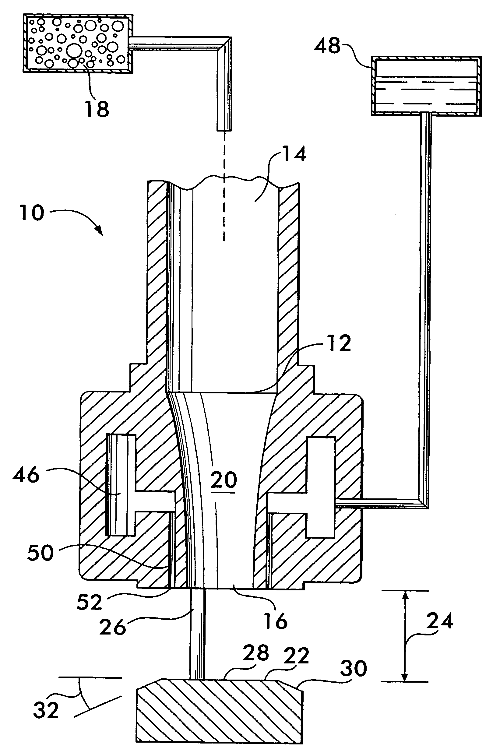
[0021]FIG. 1 shows a longitudinal sectional view of a high velocity low pressure emitter 10 according to the invention. Emitter 10 comprises a convergent nozzle 12 having an inlet 14 and an outlet 16. Outlet 16 may range in diameter between about ⅛ inch to about 1 inch for many applications. Inlet 14 is in fluid communication with a pressurized gas supply 18 that provides gas to the nozzle at a predetermined pressure and flow rate. It is advantageous that the nozzle 12 have a curved convergent inner surface 20, although other shapes, such as a linear tapered surface, are also feasible.

[0022] A deflector surface 22 is positioned in spaced apart relation with the nozzle 12, a gap 24 being established between the deflector surface and the nozzle outlet. The gap may range in size between about 1 / 10 inch to about ¾ inches. The deflector surface 22 is held in spaced relation from the nozzle by one or more support legs 26.

[0023] Preferably, deflector surface 22 comprises a flat surface p...


PUM


Abstract

An emitter for atomizing and discharging a liquid entrained in a gas stream is disclosed. The emitter has a nozzle with an outlet facing a deflector surface. The nozzle discharges a gas jet against the deflector surface. The emitter has a duct with an exit orifice adjacent to the nozzle outlet. Liquid is discharged from the orifice and is entrained in the gas jet where it is atomized. A method of operating the emitter is also disclosed. The method includes establishing a first shock front between the outlet and the deflector surface, a second shock front proximate to the deflector surface, and a plurality of shock diamonds in a liquid-gas stream discharged from the emitter.

Description

CROSS-REFERENCE TO RELATED APPLICATIONS [0001] This application is based on and claims priority to U.S. Provisional Application No. 60 / 689,864, filed Jun. 13, 2005 and U.S. Provisional Application No. 60 / 776,407, filed Feb. 24, 2006.FIELD OF THE INVENTION [0002] This invention concerns devices for emitting atomized liquid, the device injecting the liquid into a gas flow stream where the liquid is atomized and projected away from the device. BACKGROUND OF THE INVENTION [0003] Devices such as resonance tubes are used to atomize liquids for various purposes. The liquids may be fuel, for example, injected into a jet engine or rocket motor or water, sprayed from a sprinkler head in a fire suppression system. Resonance tubes use acoustic energy, generated by an oscillatory pressure wave interaction between a gas jet and a cavity, to atomize liquid that is injected into the region near the resonance tube where the acoustic energy is present. [0004] Resonance tubes of known design and opera...

Claims


Application Information

Patent Timeline
IPC IPC(8): B05B1/26B05B15/00B05B1/34A62C99/00
CPCA62C31/005A62C31/02A62C35/60A62C35/64B05B7/0892B05B1/265B05B7/08B05B7/0853A62C99/0072A62C37/08A62C37/10A62C35/58A62C35/68A62C31/00
Inventor REILLY, WILLIAM J.BALLARD, ROBERT J.IDE, STEPHEN R.
Owner VICTAULIC
Why Eureka
Try Eureka