
Transmit antenna multiplexing for vehicular passive entry systems

a vehicular and passive entry technology, applied in the field of multi-channel wireless broadcast signals, can solve the problems of reducing the expected operating life reducing the cost of the passive entry system, and reducing the distortion of the signal, so as to reduce the distortion and the effect of reducing the distortion and reducing the distortion

Inactive Publication Date: 2006-12-14
LEAR CORP
View PDF10 Cites 27 Cited by
  • Summary
  • Abstract
  • Description
  • Claims
  • Application Information

AI Technical Summary

Benefits of technology

The present invention allows for the cost-effective and reliable coupling of multiple antennas in a wireless communication system for vehicles. It reduces distortion and enables the steering of antenna signals to any selected ones simultaneously with equalization. The invention includes a coupler with two saturable reactors and current sources for independently controlling the attenuation of signals to each antenna. A controller is used to command the current sources. The technical effects of the invention are improved performance and reliability of wireless communication systems for vehicles.

Problems solved by technology

After many operating cycles, the make-and-break contacts wear out and may become permanently open or permanently closed.
These failures reduce. the expected operating lifetime of the passive entry system.
Semiconductor switches are not subject to contact wear, however other problems are encountered.
Moreover, nonlinearity of the switches leads to signal distortion that adds harmonic content to the antenna signals.
The harmonics degrade system perform making communications less reliable and reducing communication range.
The added cost and complexity of the transmitter has discouraged the introduction of functions depending upon a variable output, such as transmitting simultaneously from multiple antennas while equalizing their relative outputs to shape the coverage area of an RF broadcast.

Method used


Image

  • Transmit antenna multiplexing for vehicular passive entry systems
  • Transmit antenna multiplexing for vehicular passive entry systems
  • Transmit antenna multiplexing for vehicular passive entry systems

Examples


Embodiment Construction

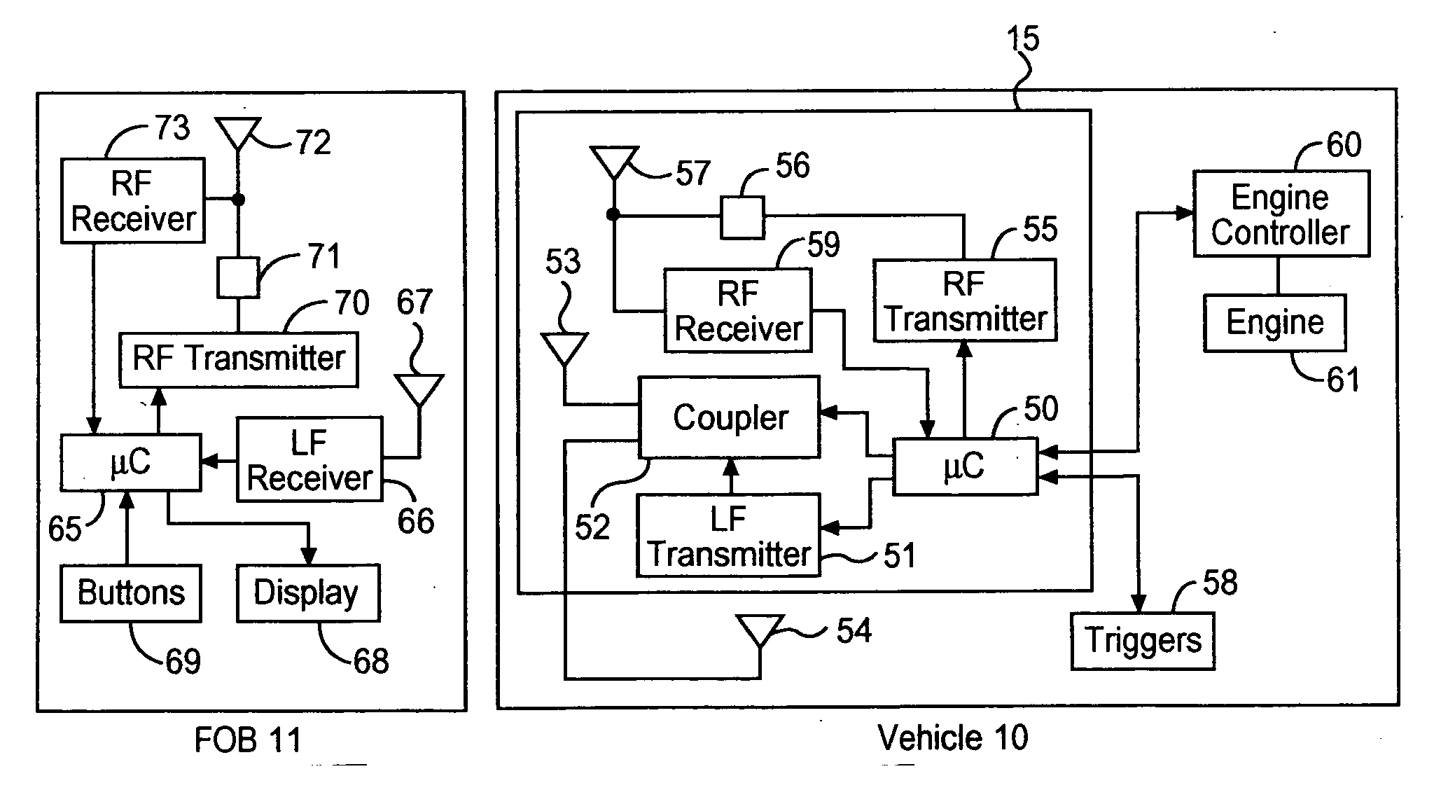
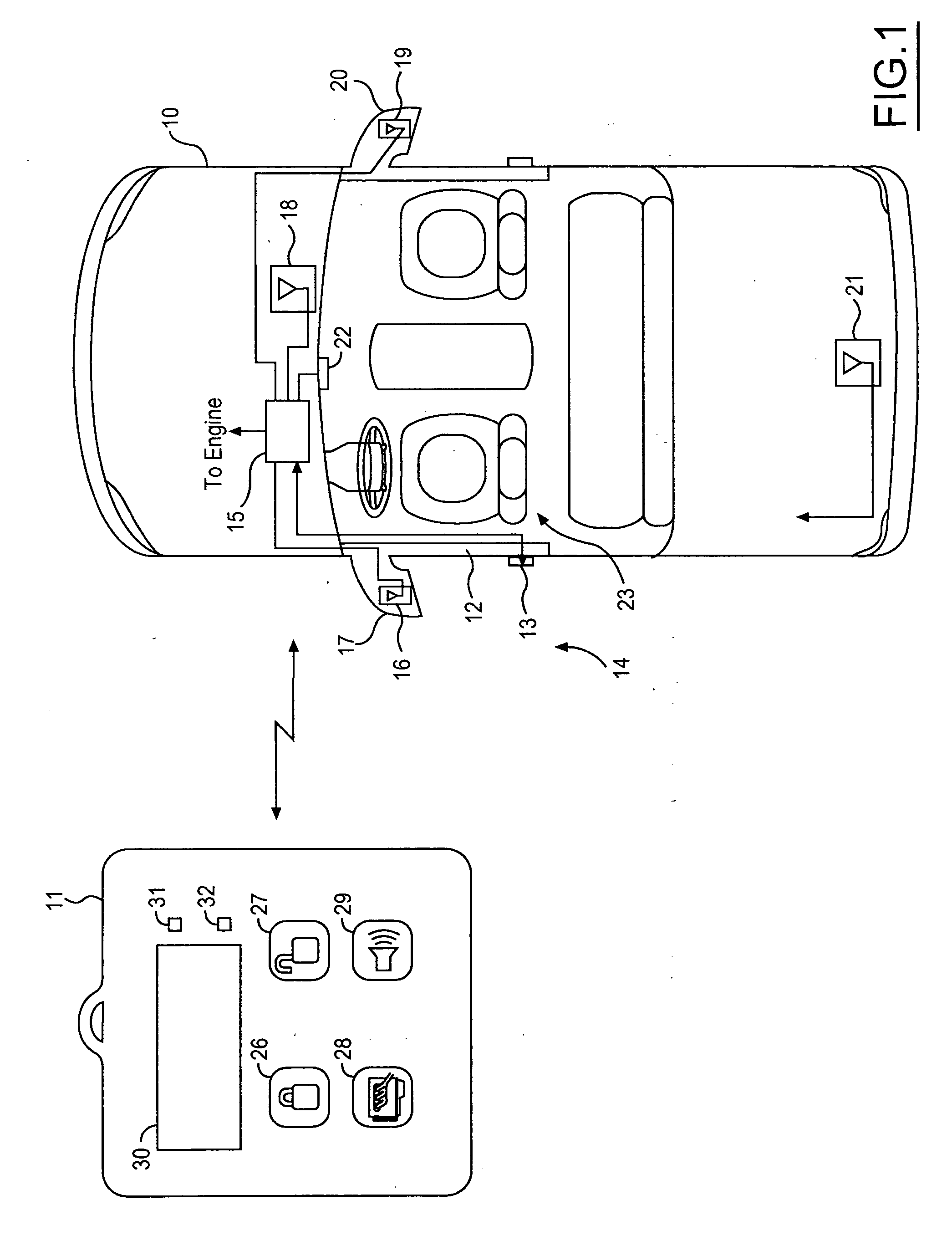
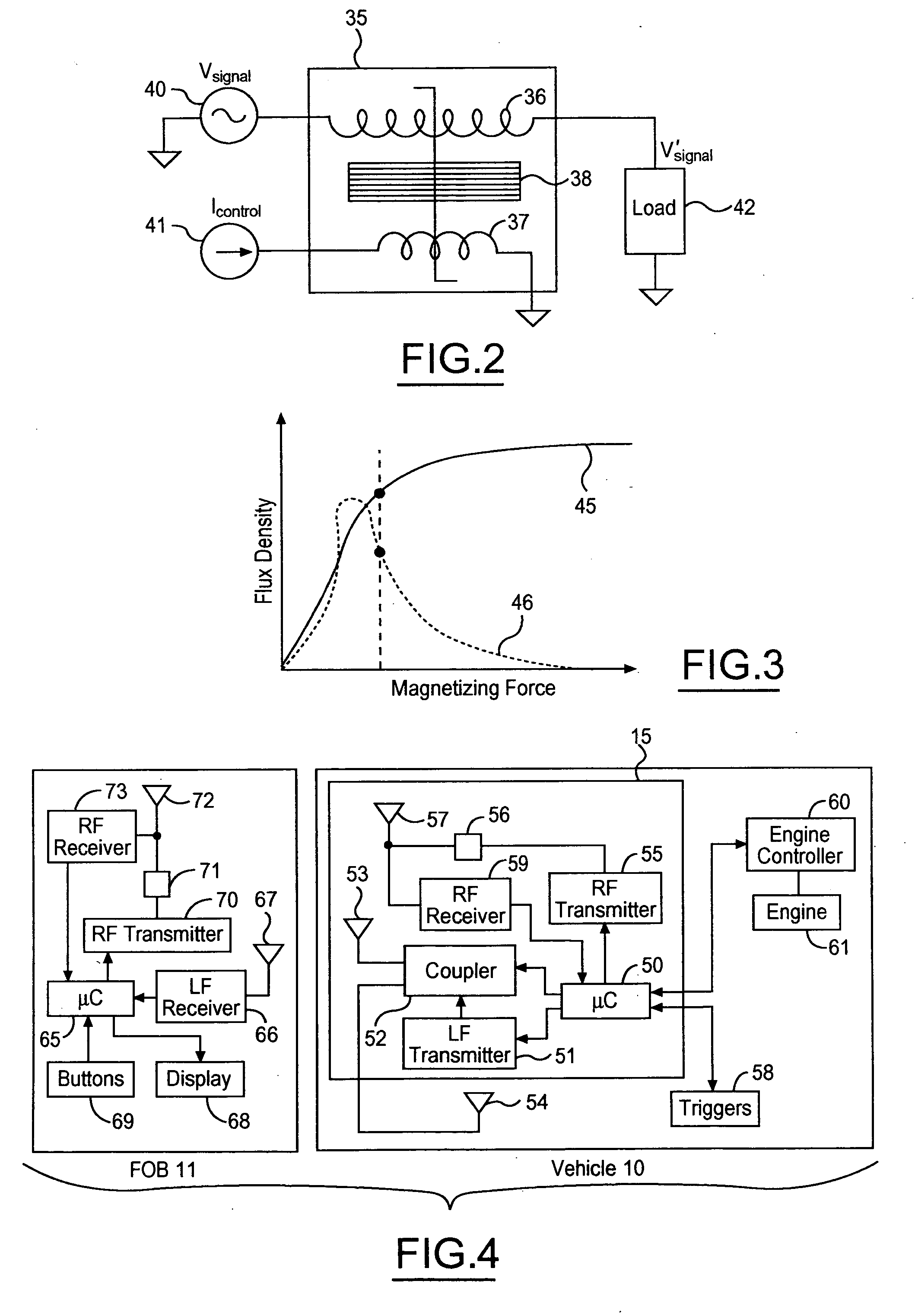
[0026] Referring to FIG. 1, a vehicle 10 communicates with a plurality of remote fobs such as a fob 11 which operates as both an RKE button-operated transmitter and a passive entry transponder. Vehicle entry via a door 12 having a door latch 13 may be obtained when a user carrying fob 11 is present at an exterior region 14. A passive entry electronic module 15 functions as a base station that is coupled to an exterior antenna 16 (mounted in a driver's side view mirror 17), an interior antenna 18 (mounted in a vehicle instrument panel), an exterior antenna 19 (mounted in a passenger side view mirror 20, and a trunk-mounted exterior antenna 21.

[0027] Door latch module 13 may include an activation switch and a lock actuator mechanism which are both coupled to module 15. By lifting the door handle, a user generates a door unlock request that causes module 15 to interrogate for an authorized fob. An engine start switch 22 may also be provided on the instrument panel and is coupled to mo...


PUM


Abstract

An antenna coupler for a wireless communication system in a vehicle couples a transmit signal source to a plurality of antennas arranged within the vehicle. A first saturable reactor has a first load winding and a first control winding wound on a first saturable core, the first load winding coupling the signal source to a first antenna. A first current source is coupled to the first control winding for providing a selected current to the first control winding. A second saturable reactor has a second load winding and a second control winding wound on a second saturable core, the second load winding coupling the signal source to a second antenna. A second current source is coupled to the second control winding for providing a selected current to the second control winding. A controller is coupled to the first and second current sources for commanding the first and second selected currents to selectably attenuate or non-attenuate a transmit signal from the transmit signal source to each respective antenna.

Description

CROSS REFERENCE TO RELATED APPLICATIONS [0001] Not Applicable. STATEMENT REGARDING FEDERALLY SPONSORED RESEARCH [0002] Not Applicable. BACKGROUND OF THE INVENTION [0003] The present invention relates in general to multiplexing wireless broadcast signals among a plurality of antennas, and, more specifically, to a vehicular passive entry system driving selected ones of a plurality of antennas disposed in a vehicle. [0004] It is well known in the automotive industry to provide for remote vehicle access, such as through the use of remote keyless entry (RKE) systems. RKE systems may be characterized as active or passive in nature. In an active system, a switch or pushbutton on a remote transmitter must be activated by an operator in order to have a desired remote function performed, such as locking or unlocking the vehicle doors. In contrast, a passive entry system does not require a pushbutton activation by an operator in order to have a desired remote function performed. [0005] In remo...

Claims


Application Information

Patent Timeline
Patent Type & Authority Applications(United States)
IPC IPC(8): H01Q1/32
CPCH01Q1/3241H01Q21/28H01Q1/3291H01Q1/3266B60R25/00H03H7/487H03K17/81
Inventor LEMENSE, THOMAS J.GHABRA, RIADTANG, QINGFENG
Owner LEAR CORP
Learn More