
Method for fixed pattern noise reduction in infrared imaging cameras

a technology of fixed pattern noise and infrared imaging, which is applied in the field of imaging systems, can solve the problems of difficult processing of roic output signal, non-uniform response of individual microbolometers to uniform incident infrared radiation, and spatial non-uniformity, and achieve the effect of reducing the level of fpn

Active Publication Date: 2006-12-14
JOHN FLUKE MFG CO INC
View PDF14 Cites 92 Cited by
  • Summary
  • Abstract
  • Description
  • Claims
  • Application Information

AI Technical Summary

Benefits of technology

The present invention relates to methods for correcting FPN (fixed pattern noise) in IR imaging cameras. The methods involve receiving data from an array of IR sensors and using predetermined FPN data to correct the data. The correction is done by selecting a strength level that reduces FPN levels in the data. The method may also involve calculating an objective function value for each strength level to determine the level of FPN remaining in the data, and selecting the strength level with the lowest objective function value as the selected strength level to correct the data. The technical effect of the invention is to improve the quality of IR imaging cameras by reducing FPN levels in the data.

Problems solved by technology

Individual microbolometers will have non-uniform responses to uniform incident infrared radiation, even when the bolometers are manufactured as part of a microbolometer FPA.
This is commonly referred to as spatial non-uniformity, and is due to the variations in a number of critical performance characteristics of the microbolometer detectors.
The resulting ROIC output signal is difficult to process, as it requires system interface electronics having a very high dynamic range.
One source of error in microbolometer focal plane arrays is the variation in “responsivity” of each microbolometer with changes in temperature.
Because of this, it cannot be removed by averaging data from multiple frames.
However, the two-point correction method usually only works well when the IRFPA has relatively small pixel-to-pixel variations in responsivity and offset, and when the IRFPA is temperature stabilized.
Camera systems that utilize a shutter that is located between the IRFPA and the lens (which is a common configuration) are particularly susceptible to fixed pattern artifacts caused by pixel-to-pixel variations in responsivity.

Method used


Image

  • Method for fixed pattern noise reduction in infrared imaging cameras
  • Method for fixed pattern noise reduction in infrared imaging cameras
  • Method for fixed pattern noise reduction in infrared imaging cameras

Examples


Embodiment Construction

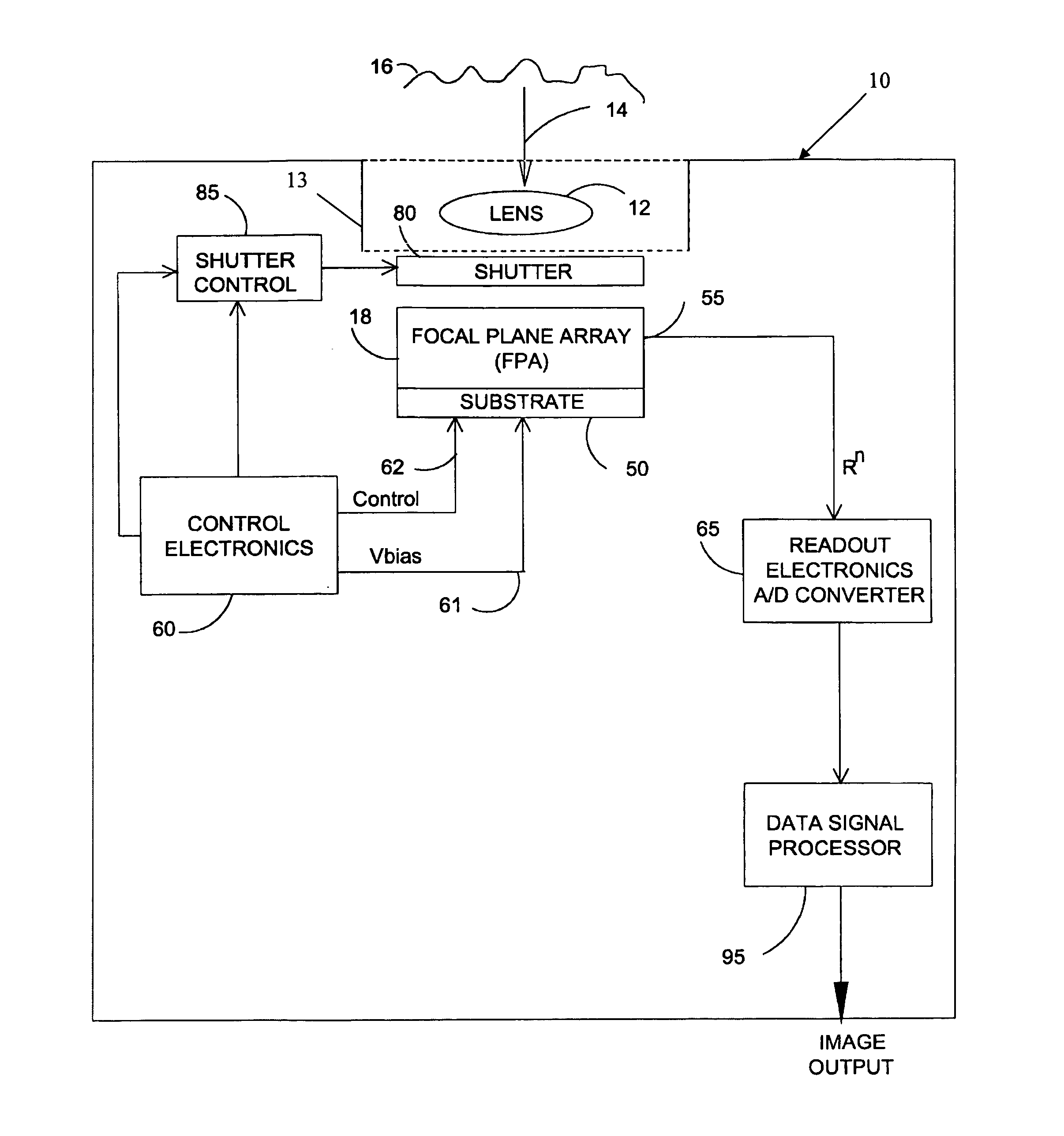
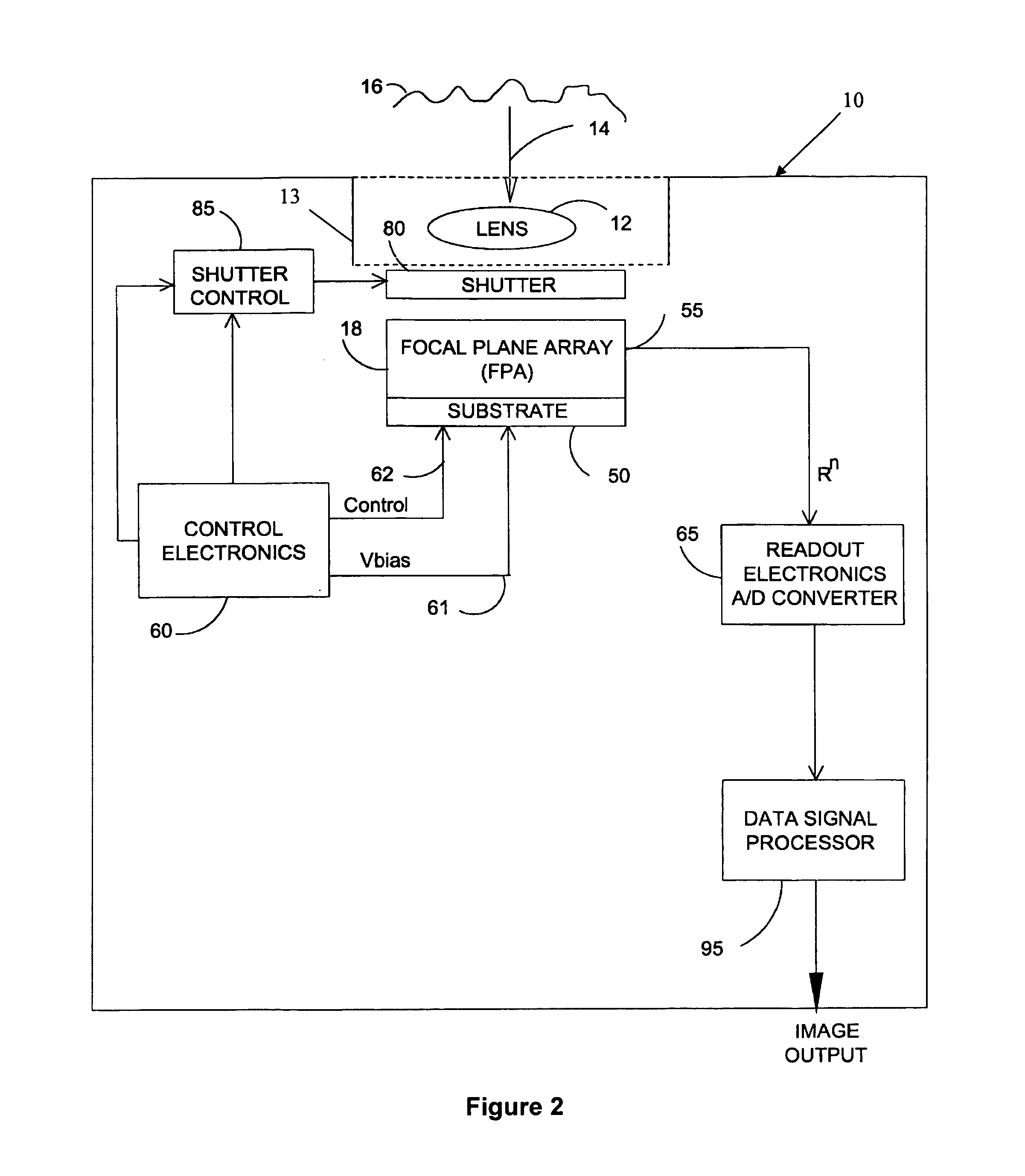
[0031]FIG. 2 shows a functional block diagram of a portable camera 10 similar to that illustrated in the U.S. Pat. No. 6,023,061. A compound lens 12 (here shown as a single lens for ease of illustration) surrounded by lens barrel 13 collects infrared energy 14 from a scene 16 and images the scene onto a two-dimensional uncooled focal plane array (FPA) 18. In some embodiments, the FPA is stabilized with known TE-stabilizers. The FPA 18 is comprised of an M.times.N array of microbolometer detectors or pixels on a semiconductor substrate 50. Substrate 50 commonly may include integrated circuit architecture within the substrate for providing sensor bias and detector output multiplexing functions as desired. Each detector or pixel may be manufactured as a microbridge such as described in the aforementioned U.S. Pat. No. 5,286,976. These microbolometers are manufactured directly onto the substrate by known methods.

[0032] Control electronics 60 is coupled to the FPA 18 through one or more...


PUM


Abstract

Methods and systems for correcting fixed pattern noise (FPN) in infrared (IR) imaging cameras. The methods and systems include correcting IR sensor data different strength levels of FPN data and selecting the particular strength level that produces corrected data with the least amount of FPN. The correction may occur over several frames of IR sensor data in order to find an optimal strength level for correction.

Description

CROSS-REFERENCE TO RELATED APPLICATION [0001] This application claims priority to co-pending U.S. Patent Application Ser. No. 60 / 685,010, filed May 26, 2005, entitled Method for Fixed Pattern Noise Reduction in Infrared Focal Plane Arrays, and said application is incorporated herein by reference in its entirety.FIELD OF THE INVENTION [0002] Embodiments of the present invention relate generally to imaging systems, such as infrared imaging cameras. More specifically, certain embodiments of the present invention are directed to methods and systems for correcting fixed pattern noise (FPN) errors in an infrared imaging camera. BACKGROUND OF THE INVENTION [0003] An infrared detector called the “bolometer,” now well known in the art, operates on the principle that the electrical resistance of the bolometer material changes with respect to the bolometer temperature, which in turn changes in response to the quantity of absorbed incident infrared radiation. These characteristics can be exploi...

Claims


Application Information

Patent Timeline
Patent Type & Authority Applications(United States)
IPC IPC(8): H04N5/33H04N5/217H04N5/365
CPCH04N5/33H04N5/365H04N5/3656H04N5/3653H04N5/3655H04N5/3651H04N25/671H04N25/672H04N25/673H04N25/674H04N23/23H04N25/677H04N25/67
Inventor ANDERSON, SHANE M.
Owner JOHN FLUKE MFG CO INC
Learn More