Self-alignment of radiographic imaging system

Inactive Publication Date: 2006-12-14
VAREX IMAGING CORP
View PDF9 Cites 28 Cited by
  • Summary
  • Abstract
  • Description
  • Claims
  • Application Information

AI Technical Summary

Problems solved by technology

In such imaging systems, the x-ray source and detector are aligned in fixed positions and typically not moveable relative to each other or able to repositioned and / or realigned.
There are also instances that it is impractical to move objects such as a pipeline in use to an examination room for inspection.

Method used


Image

  • Self-alignment of radiographic imaging system
  • Self-alignment of radiographic imaging system
  • Self-alignment of radiographic imaging system

Examples


Embodiment Construction

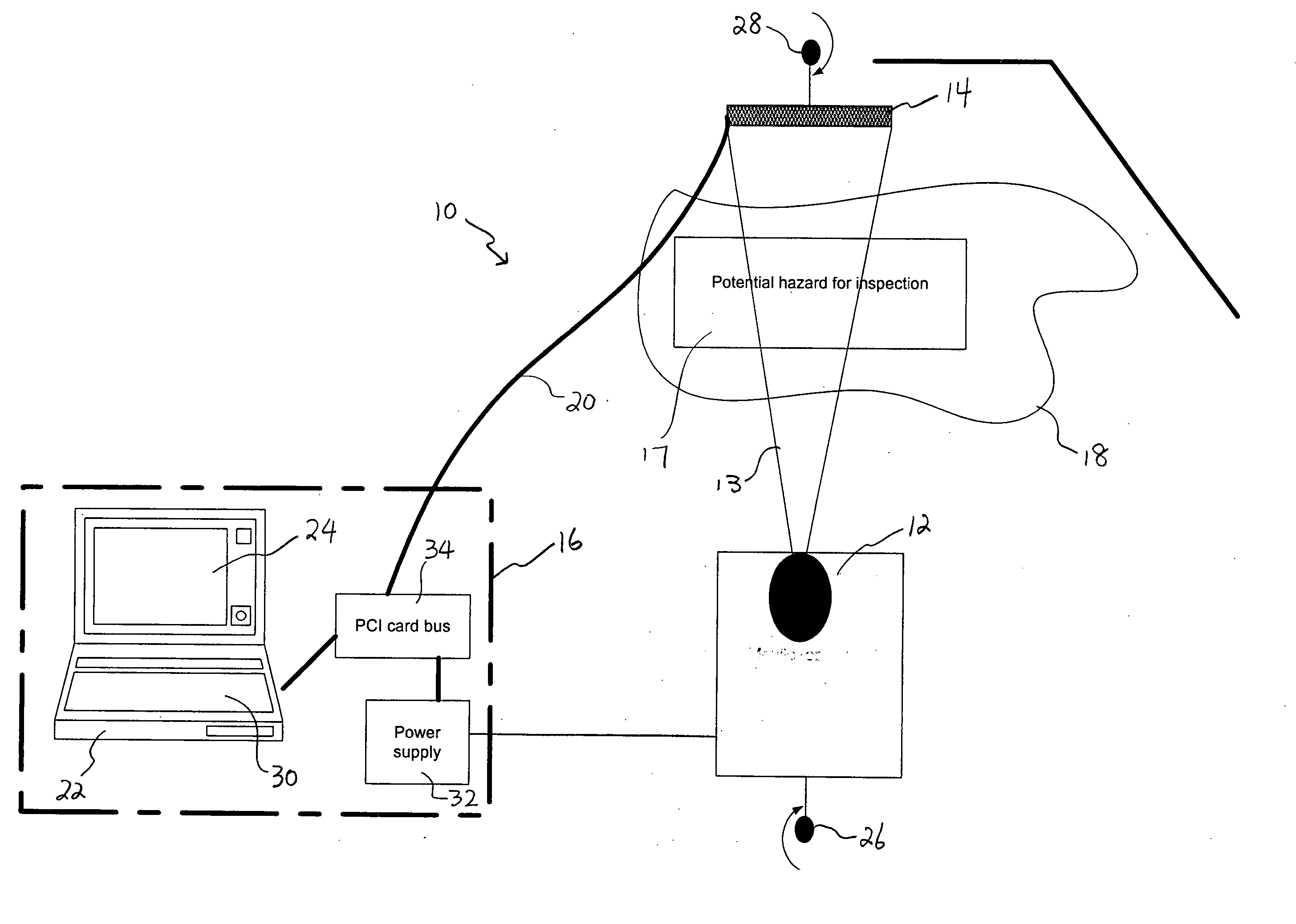
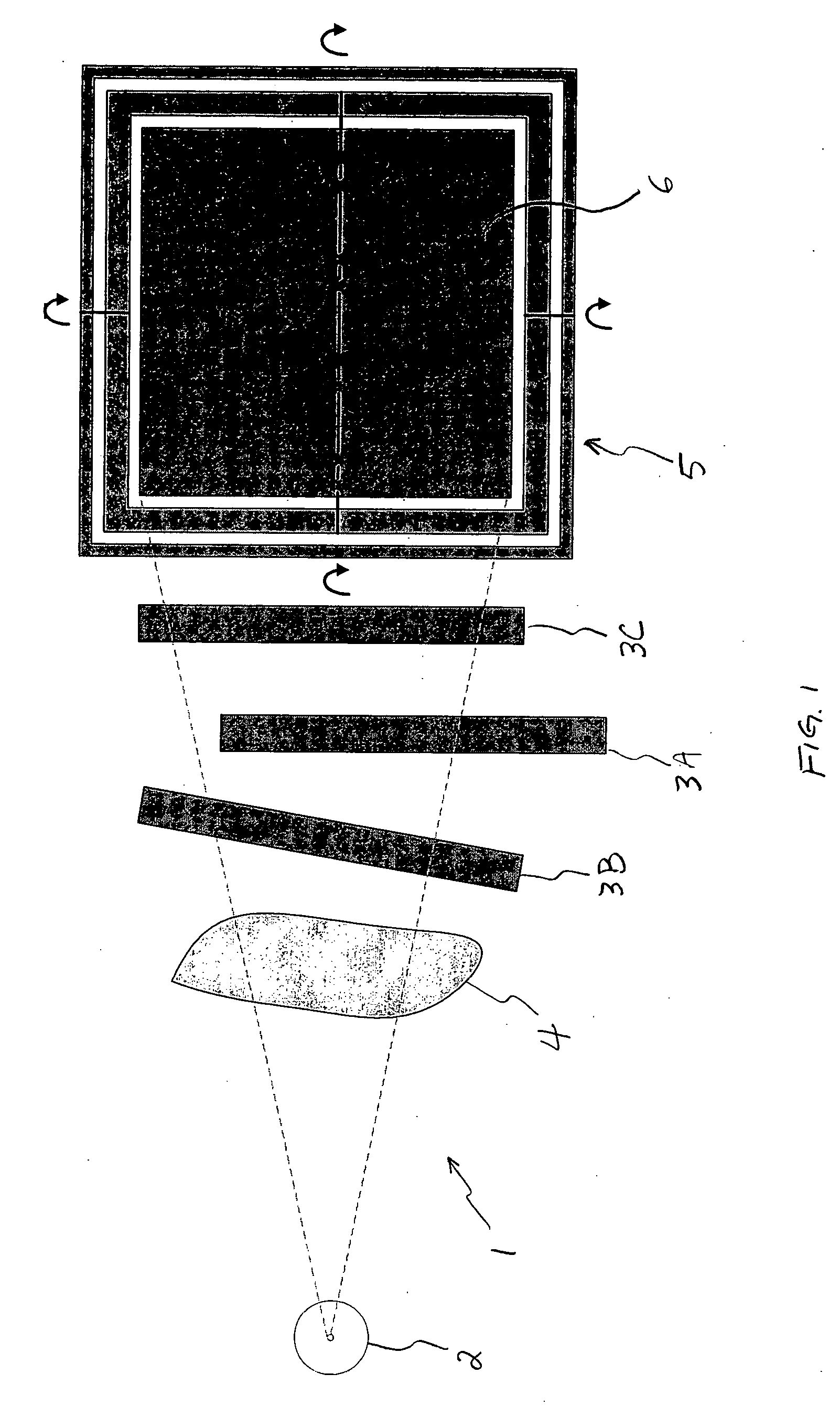
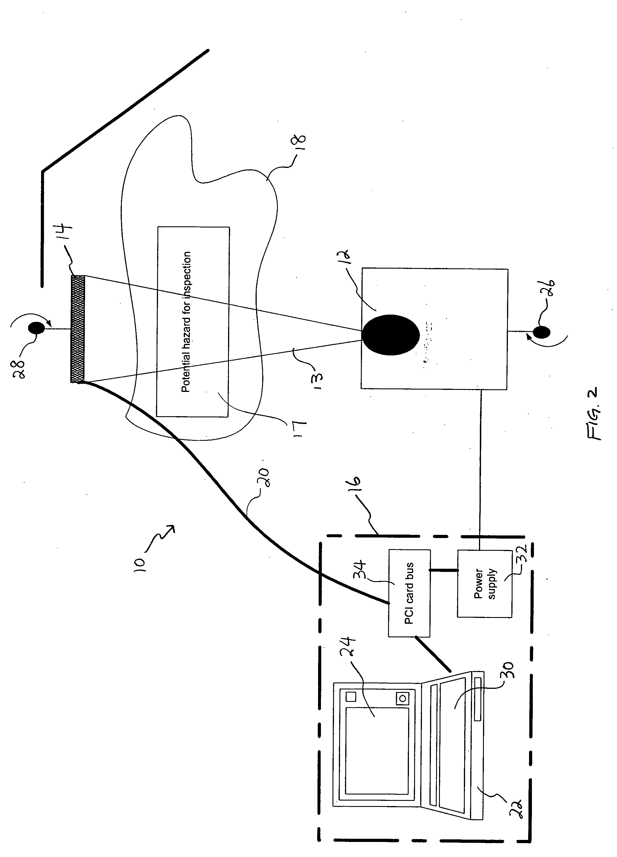
[0016] Various embodiments of the present invention are described hereinafter with reference to the figures. It should be noted that the figures are not drawn to scale and elements of similar structures or functions are represented by like reference numerals throughout the figures. It should also be noted that the figures are only intended to facilitate the description of specific embodiments of the invention. They are not intended as an exhaustive description of the invention or as a limitation on the scope of the invention. In addition, an aspect described in conjunction with a particular embodiment of the present invention is not necessarily limited to that embodiment and can be practiced in any other embodiments of the present invention. For instance, in the following description, the present invention is described with embodiments of an x-ray imaging system. It will be appreciated that the claimed invention can be used not only for x-ray imaging systems, but also for any other ...


PUM


Abstract

An imaging system 10 is provided comprising an x-ray source 12, a detector 14, and an alignment device 38 adapted to align the detector 14 with the x-ray source 12 using an x-ray beam transmitted from the x-ray source 12. A method of positioning and aligning an imaging system is also provided.

Description

FIELD OF THE INVENTION [0001] This invention relates generally to radiographic imaging systems and methods, and in particular, to systems and methods for automatically positioning and aligning radiographic imaging systems. BACKGROUND [0002] Radiographic imaging such as X-ray imaging has been used for a wide variety of applications in various fields. A typical x-ray imaging system includes an x-ray source generating x-ray beams to irradiate a region of interest (ROI), and an x-ray detector detecting the x-ray beams passing through the ROI. To achieve an x-ray image with sufficient information, precise positioning and alignment of the imaging system, especially between the x-ray source and detector, is required. In prior art imaging systems, the x-ray source and detector are physically attached to each other in a rigid and bulky structure such as an enclosed housing. In such imaging systems, the x-ray source and detector are aligned in fixed positions and typically not moveable relati...

Claims


Application Information

Patent Timeline
IPC IPC(8): A61B6/08
CPCA61B6/08A61B6/4233A61B6/548G01N23/04A61B6/587
Inventor HARDESTY, DANIEL M.
Owner VAREX IMAGING CORP
Why Eureka
Try Eureka