Pattern comparison inspection method and pattern comparison inspection device

a technology of pattern comparison and inspection method, applied in the direction of photomechanical equipment, instruments, image enhancement, etc., can solve the problems of reducing fabrication yield and taking a long time to complete all, and achieve the effect of enhancing inspection speed and inspection rang

Inactive Publication Date: 2006-12-14
TOKYO SEIMITSU
View PDF2 Cites 79 Cited by
  • Summary
  • Abstract
  • Description
  • Claims
  • Application Information

AI Technical Summary

Benefits of technology

[0046] According to the present invention, the inspection region where repeated patterns are compared with each other can be enlarged as far as possible in a pattern comparison inspection, which checks for the presence or absence of a pattern defect, by comparing the repeated patterns with each other within the inspection target pattern.
[0047] Further, as in the pattern comparison inspection methods according to the third and fourth modes and the pattern comparison inspection apparatuses according to the seventh and eighth modes of the present invention, if the inspection range is determined by using the defect candidates detected for the defect inspection, the amount of computation required to compare the pixel values of the captured image to determine the inspection range can be reduced, which contributes to enhancing the inspection speed.

Problems solved by technology

In the fabrication process of semiconductor devices, since many layers of patterns are formed on the wafer 200, not only does it take a long time to complete all the fabrication steps but, if there is a critical defect even in one layer, the affected die is rendered defective, which decreases the fabrication yield.

Method used


Image

  • Pattern comparison inspection method and pattern comparison inspection device
  • Pattern comparison inspection method and pattern comparison inspection device
  • Pattern comparison inspection method and pattern comparison inspection device

Examples


first embodiment

[0082] Embodiments of the present invention will be described below with reference to the accompanying drawings. FIG. 4 is a diagram schematically showing the configuration of a pattern comparison inspection apparatus according to the present invention.

[0083] The pattern comparison inspection apparatus 10 comprises: a stage 21 for holding thereon a wafer 22 on which circuit patterns or the like containing repeated patterns of memory cells, etc. are formed; an imaging portion 20, such as a one-dimensional image sensor, for capturing an image of the patterns formed on the wafer 22; and a stage controller 29 for moving the stage 21 so that the wafer 22 is scanned by the imaging portion 20 in order for the imaging portion 20 to capture the image of the patterns across the entire surface of the wafer 22.

[0084] The pattern comparison inspection apparatus 10 further comprises: an A / D converter 23 which converts the captured analog image signal into an image signal in digital form; an imag...

second embodiment

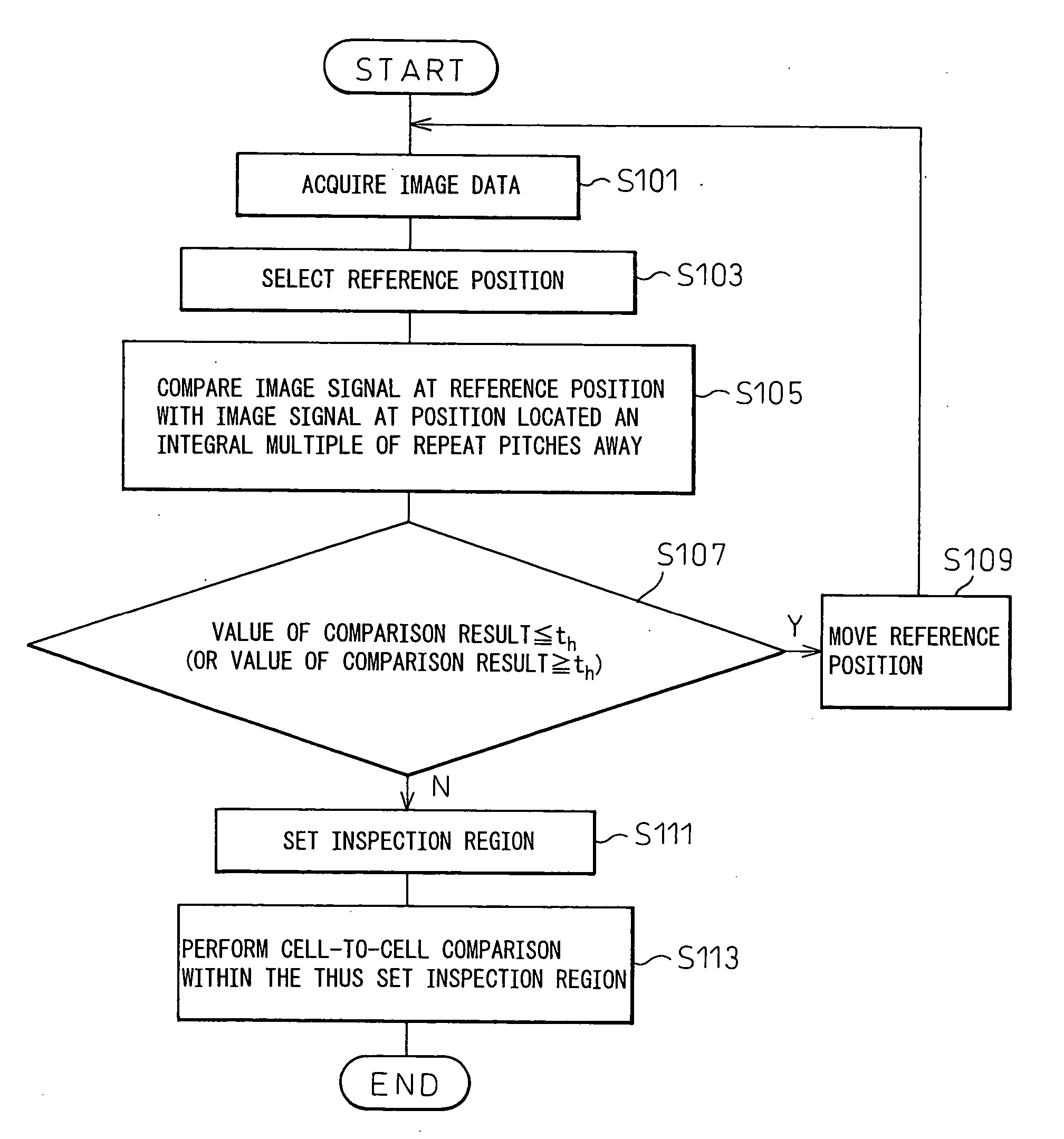
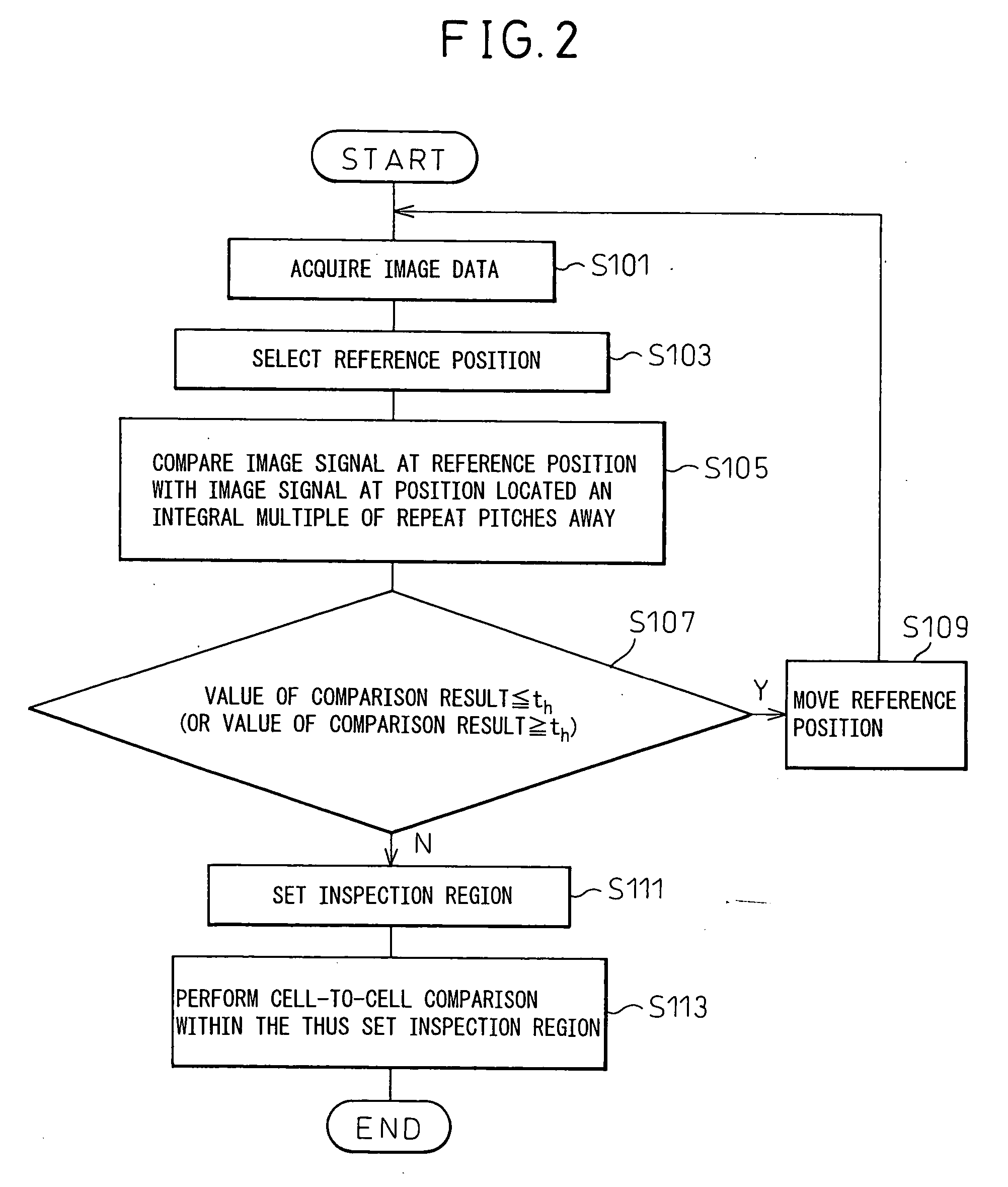
[0140] As in the methods previously described with reference to FIGS. 6 and 12, instead of determining in step S169 in the method of FIG. 15 that the value of the comparison result has dropped below the predetermined threshold value th, and setting the reference position as the boundary of the inspection region when the value of the comparison result has dropped below the predetermined threshold value th, a determination may be made as to whether the amount of change or rate of change between the result of the comparison performed in the previous loop and the result of the comparison performed in the present loop exceeds a predetermined threshold value and, when this amount of change or rate of change exceeds the predetermined threshold value, the present reference position may be set as the boundary of the inspection region. FIG. 16 shows a flowchart of the pattern comparison inspection method according to the present invention, for explaining such operation of the pattern comparis...

third embodiment

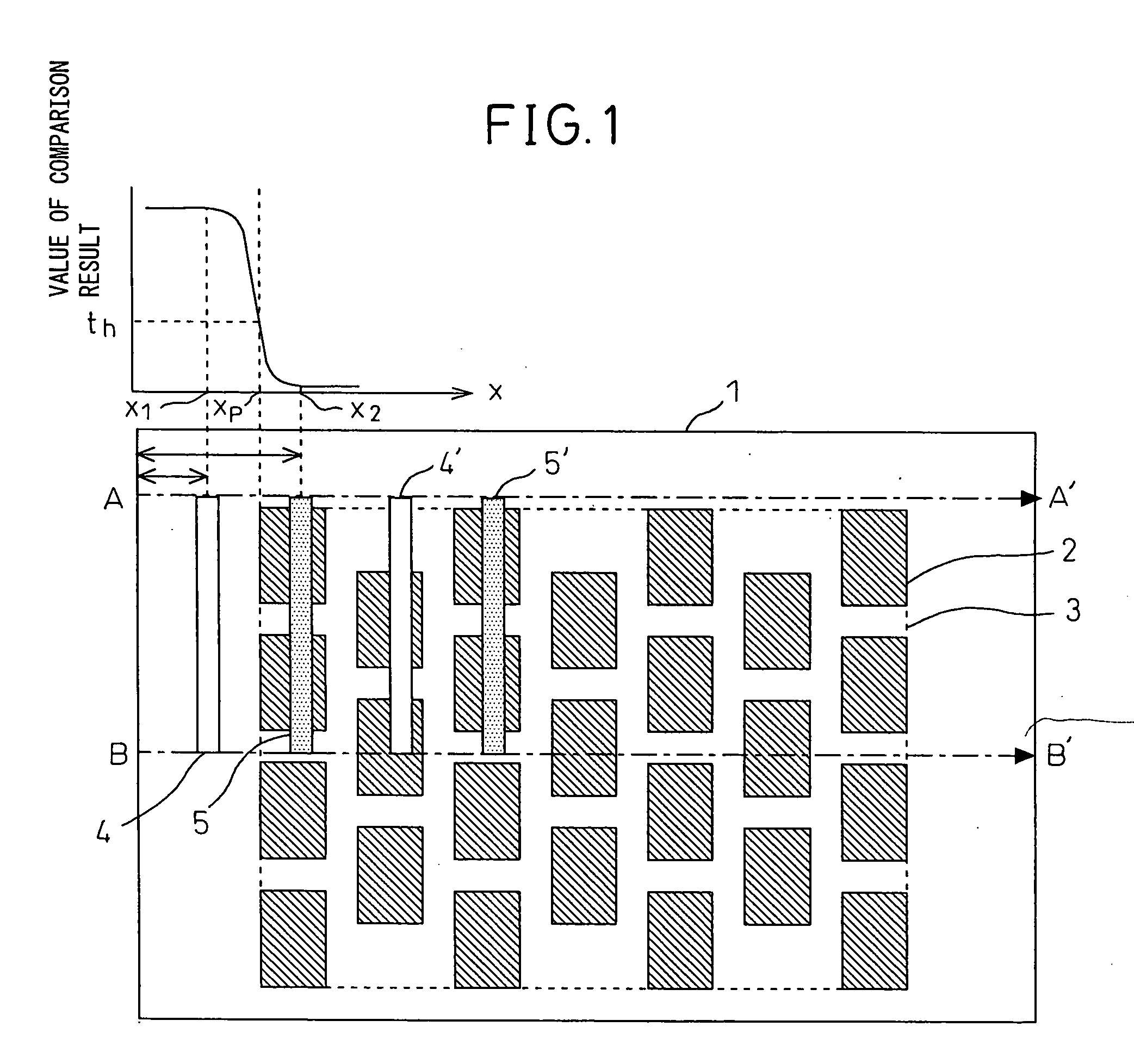
[0148]FIG. 20 is a diagram schematically showing the configuration of a pattern comparison inspection apparatus according to the present invention. The pattern comparison inspection apparatus 10 of this embodiment captures an image of a circuit pattern or the like that is formed on a wafer 22 and that contains a repeated pattern region such as a memory cell region, and compares a given threshold value with a difference value taken between two pixels located at positions separated from each other by an integral multiple of the repeat pitch in the captured image. Then, a defect candidate map is generated by taking any pixel for which the difference is larger than the threshold value as a defect candidate; next, in the entire range of the defect candidate map, a region where the frequency of occurrence of such defect candidates is lower than a predetermined frequency is determined as the repeated pattern region, while a region where the frequency is higher is determined as a region out...


PUM

PropertyMeasurementUnit
distanceaaaaaaaaaa
thresholdaaaaaaaaaa
opticalaaaaaaaaaa

Abstract

A pattern comparison inspection apparatus comprises: a reference position selecting portion (41) which selects from among positions on an inspection target pattern a reference position which is judged whether it should be contained in an inspection region; an image comparing portion (42) which compares an image signal at the reference position with an image signal at a position located an integral multiple of a repeat pitch away from the reference position; and an inspection region setting portion (43) which sets the inspection region by containing therein the reference position when a comparison result from the image comparing portion shows a value not greater than a prescribed threshold value. Thus, in the pattern comparison inspection apparatus which performs inspection for a pattern defect by comparing repeated patterns with each other in the inspection target pattern having a repeated pattern region, the inspection region can be enlarged within the bounds of the repeated pattern region.

Description

TECHNICAL FIELD [0001] The present invention relates to a pattern comparison inspection method and apparatus which performs inspection for a defect, etc. by comparing repeated patterns, with each other, in a pattern having repeated patterns repeated with a prescribed period (pitch) and, more particularly, to an appearance inspection method and apparatus whereby a pattern such as a photomask pattern or a pattern formed on a semiconductor wafer of a semiconductor memory or the like, having repeated cell patterns, is inspected by sequentially comparing one cell pattern with another cell pattern in the neighborhood of the one cell pattern. BACKGROUND ART [0002] It is widely practiced to generate image data by capturing an image of a formed pattern and to inspect the pattern for a defect, etc. by analyzing the image data. In particular, in the field of semiconductor fabrication, photomask inspection equipment for inspecting photomasks and appearance inspection equipment for inspecting pa...

Claims


Application Information

Patent Timeline
Patent Type & Authority Applications(United States)
IPC IPC(8): G06K9/00G01N21/95G01N21/956G03F7/20G06T7/00
CPCG01N21/95607G06T2207/30148G06T7/001G03F7/7065
Inventor ISHIKAWA, AKIO
Owner TOKYO SEIMITSU
Why Eureka
Try Eureka