
Hardware function generator support in a DSP

a function generator and hardware technology, applied in the field of digital signal processing, can solve the problems of limited function and data resolution, large amount of data stored in a rom lookup table that can quickly surpass practical size and cost limitations, and typical software implementations of function generation are relatively slow. , to achieve the effect of efficiently retrieving information, quick and efficient processing of cordic algorithm in pipeline, and low overhead

Inactive Publication Date: 2006-12-14
QUARTICS
View PDF99 Cites 8 Cited by
  • Summary
  • Abstract
  • Description
  • Claims
  • Application Information

AI Technical Summary

Benefits of technology

This approach enables fast and efficient processing of the CORDIC algorithm, reducing chip area and DSP idle cycles, and improving the implementation of DSP algorithms like Radix-2 butterfly, while avoiding extensive memory storage and enhancing computational throughput.

Problems solved by technology

Disadvantageously, the amount of data that is stored in a ROM lookup table can quickly surpass practical size and cost limitations.
By contrast, where a ROM lookup table is relatively small and inexpensive, the number of available functions and the resolution of the data available are limited.
Disadvantageously, typical software implementations of function generation are relatively slow.
Typical software routines use iterative techniques, and take relatively time consuming multiple cycles to generate a trigonometric function.
Where a conventional CORDIC is pipelined, execution can be faster, but conventional pipelined CORDICs have relatively little integration with other hardware.
Disadvantageously, other hardware, such as microprocessors and DSPs, closely monitor or control conventional pipelined CORDICs or store the results of the conventional pipelined CORDIC in relatively large and expensive memory devices.

Method used


Image

  • Hardware function generator support in a DSP
  • Hardware function generator support in a DSP
  • Hardware function generator support in a DSP

Examples


Embodiment Construction

[0028] Although this invention is described in terms of certain preferred embodiments, other embodiments that are apparent to those of ordinary skill in the art, including embodiments which do not provide all of the benefits and features set forth herein, are also within the scope of this invention. Accordingly, the scope of the present invention is defined only by reference to the appended claims.

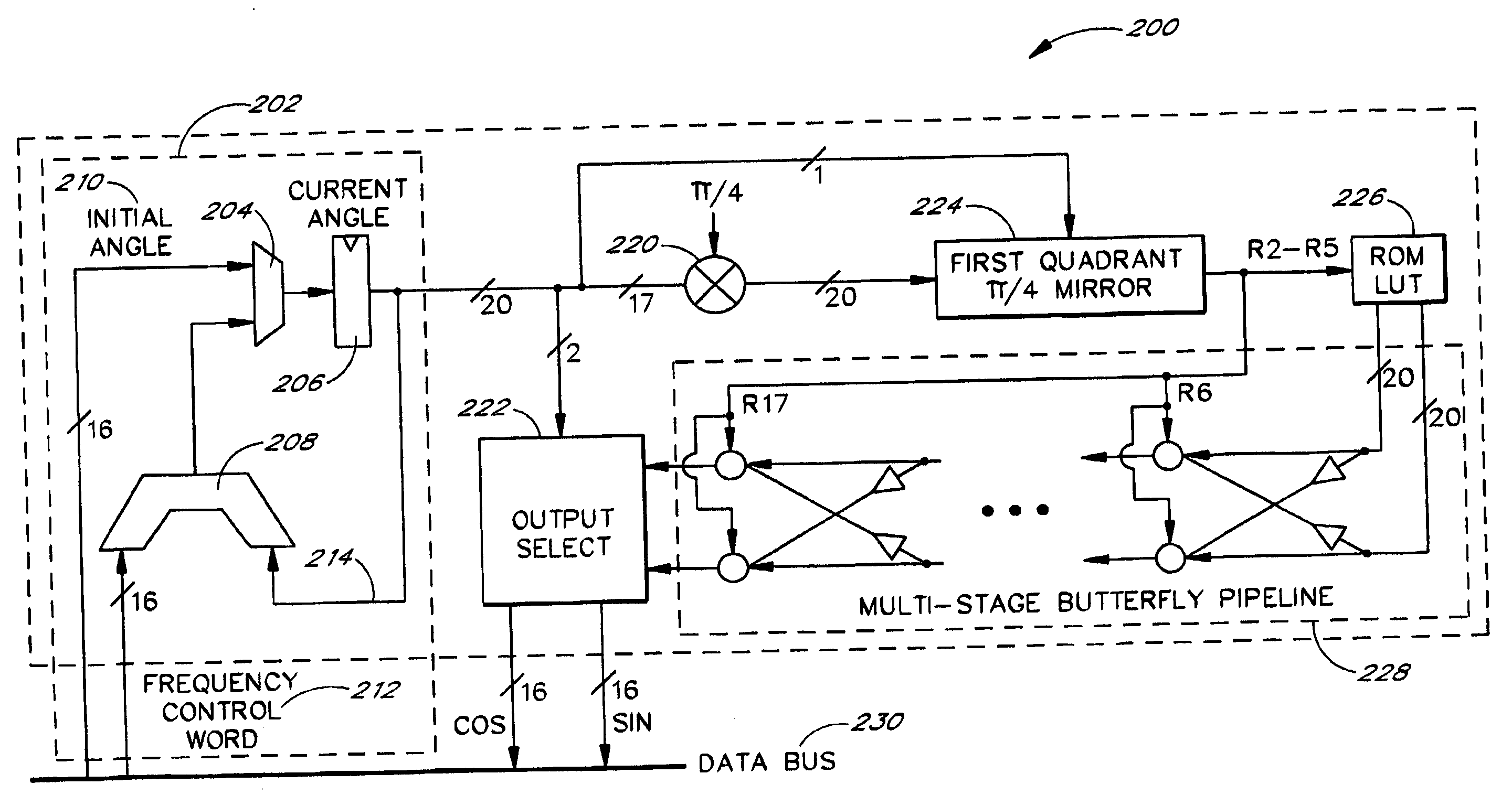
[0029] One use of a Coordinate Rotation Digital Computer (CORDIC) algorithm is to generate functions such as trigonometric, logarithmic, hyperbolic and linear functions. Another use of the CORDIC algorithm is to convert between Polar and Cartesian coordinates. The CORDIC algorithm performs vector coordinate rotations using simple iterative shifts and add / subtract operations. The general (Givens') rotation transform expressed in Equations 1A and 1B rotates a vector by an angle φ.

x′=x cos φ−y sin φ

y′=y cos φ+x sin φ.   Eqs. 1A and 1B

[0030] The transform can be rearranged as shown in Equat...


PUM


Abstract

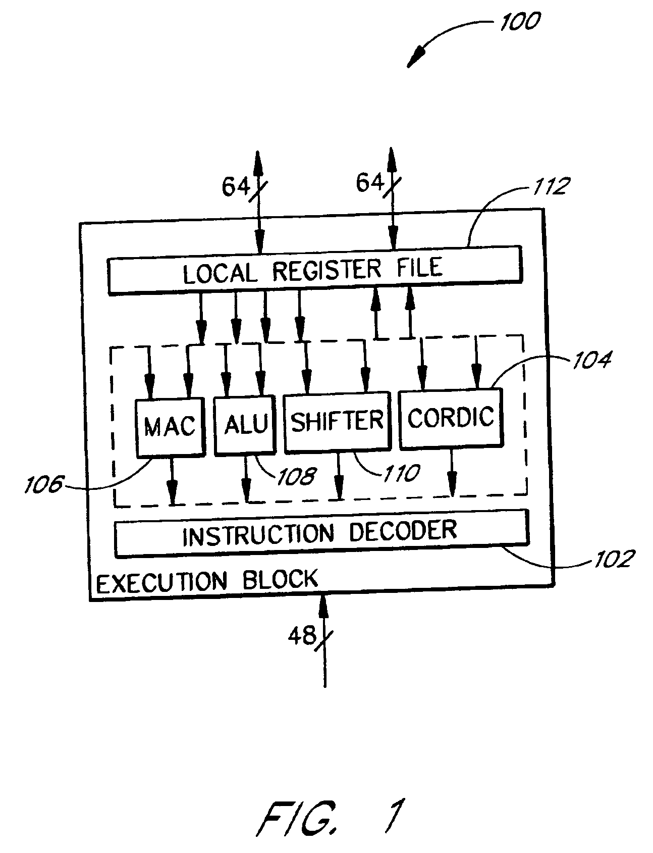
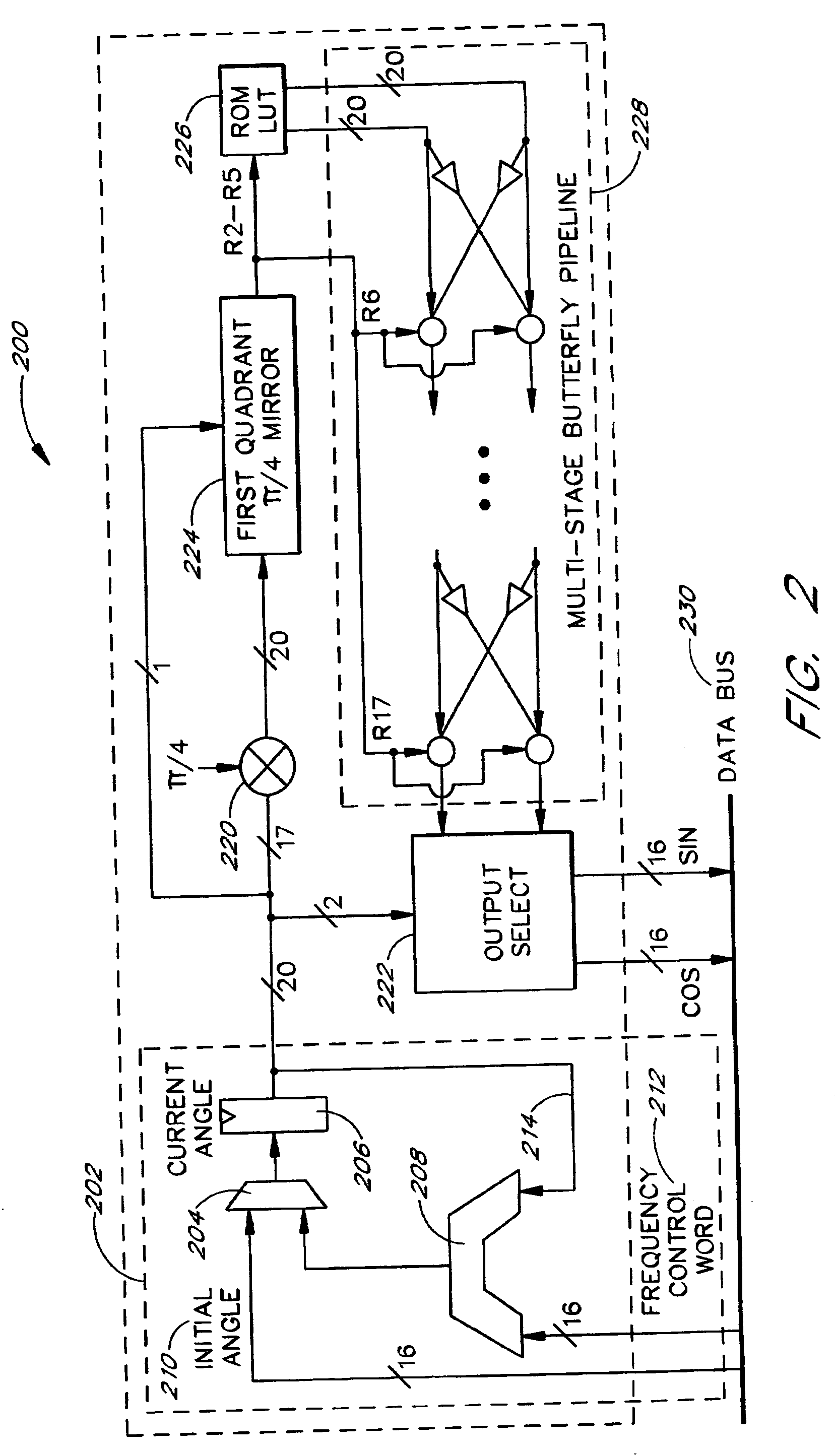
The present invention relates to digital signal processors with an integrated module configured to compute a Coordinate Rotation Digital Computer (CORDIC) in a pipeline. The pipelined module can advantageously complete computation of one CORDIC computation for each clock pulse applied to the CORDIC module, thereby providing a CORDIC computation for each clock pulse. One embodiment advantageously computes a first portion of a computation with a lookup table and a second portion in accordance with a CORDIC algorithm. Advantageously, data in a CORDIC pipeline is automatically advanced in response to read instructions and can be automatically advanced from the beginning of the pipeline to the end of the pipeline to reinitialize the pipeline. This allows information to be retrieved from the CORDIC pipeline with relatively little overhead The automatic starting and stopping of the CORDIC pipeline advantageously allows the retrieval of computations from efficient pipeline architectures on an as-needed basis.

Description

RELATED APPLICATION [0001] This application claims the benefit under 35 U.S.C. §119(e) of U.S. Provisional Application No. 60 / 231,280, filed Sep. 8, 2000, the entirety of which is hereby incorporated by reference.BACKGROUND OF THE INVENTION [0002] 1. Field of the Invention [0003] The present invention generally relates to digital signal processing. In particular, the present invention relates to a Coordinate Rotation Digital Computer (CORDIC) in a digital signal processor (DSP). [0004] 2. Description of the Related Art [0005] A Coordinate Rotation Digital Computer (CORDIC) algorithm performs vector coordinate rotations by using simple iterative shifts and add / subtract operations, which are relatively easy to implement in hardware. Advantages of the CORDIC algorithm have been well documented by U.S. Pat. No. 4,896,287 to O'Donnell, et al., U.S. Pat. No. 4,937,775 to Engeler, et al., and U.S. Pat. No. 5,684,435 to Bergen, the entireties of which are hereby incorporated by reference. [...

Claims


Application Information

Patent Timeline
Patent Type & Authority Applications(United States)
IPC IPC(8): G06F17/15G06F7/544G06F7/57G06F9/38G10L19/14
CPCG06F7/5446G06F7/57G06F2207/3884G06F9/3879G06F9/3867
Inventor KHAN, SHOAB A.HAMEED, REHANFAROOQ, HASSAN
Owner QUARTICS
Learn More