
Expansion of cross-domain addressing for PCI-express packets passing through non-transparent bridge

a cross-domain addressing and packet-based technology, applied in data switching networks, multiplex communication, instruments, etc., can solve the problems of pci-express networks that are growing in size and complexity, above plx approaches, and achieve the effect of increasing the number of domestic devices

Active Publication Date: 2006-12-14
MICROSEMI STORAGE SOLUTIONS US INC
View PDF7 Cites 75 Cited by
  • Summary
  • Abstract
  • Description
  • Claims
  • Application Information

AI Technical Summary

Benefits of technology

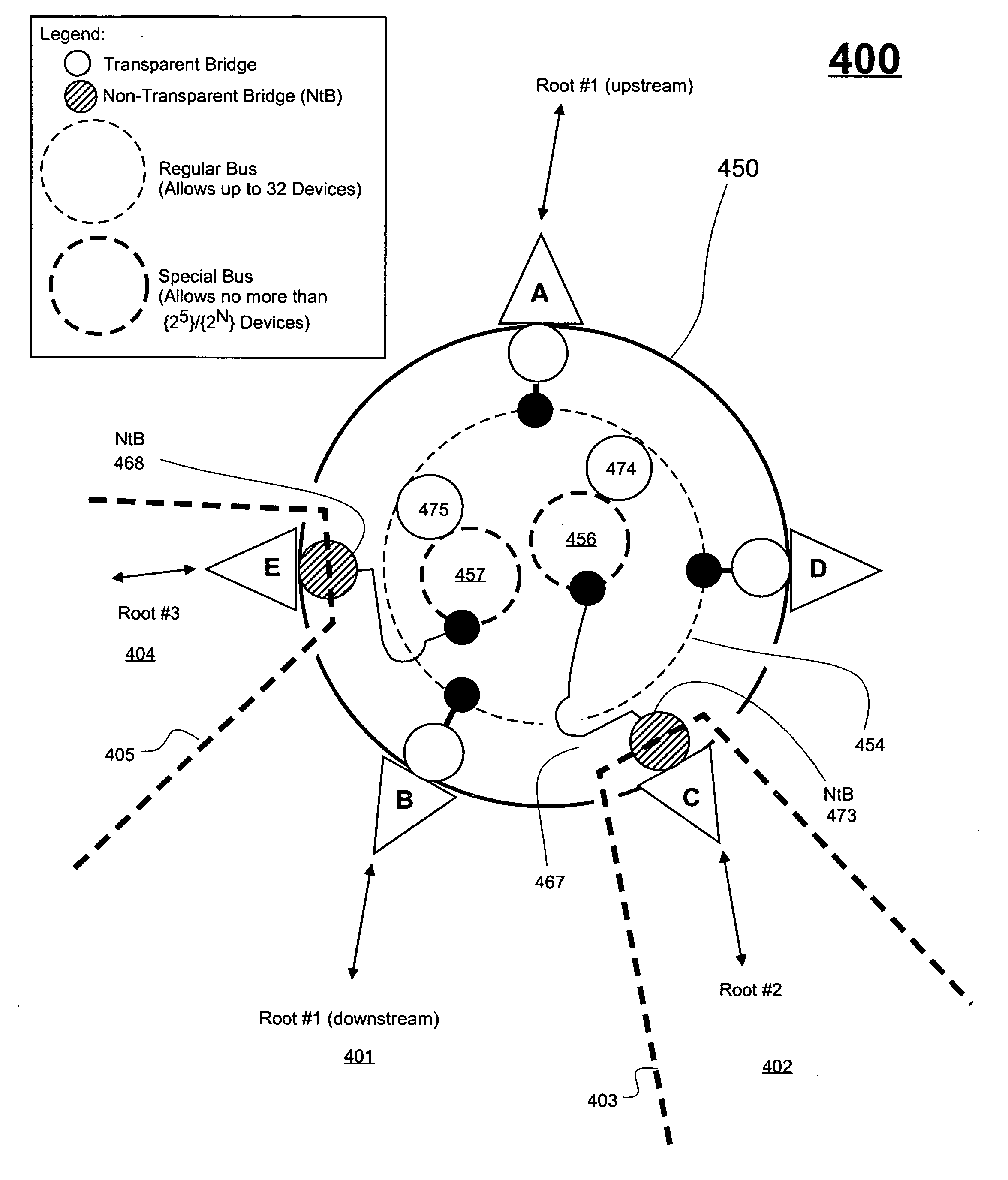
[0014] In accordance with a supplemental or alternate aspect of the present disclosure, a PCI-Express compatible switch is provided with one or more, internal and unused virtual buses (dummy buses) that sequentially bridge to a non-dummy bus on which there resides a nontransparent bridge. One or more bus-identifying bits of an ID-Tag that targets the nontransparent bridge are designated as don't-cares for purposes of addressing the nontransparent bridge if the one or more bus-identifying bits merely distinguish between the dummy bus(es) and the non-dummy bus on which the nontransparent bridge resides. The one or more bus-identifying bits that are so-designated as don't-cares are then freed for other uses, including for identifying domestic originators of cross-border, split transactions. The dummy bus(es) method may be used alone or in combination with the above, special bus(es) method to increase the number of domestic devices that can be identified as originators of cross-border, split transactions.

Problems solved by technology

PCI-Express networks continue to grow in size and complexity.
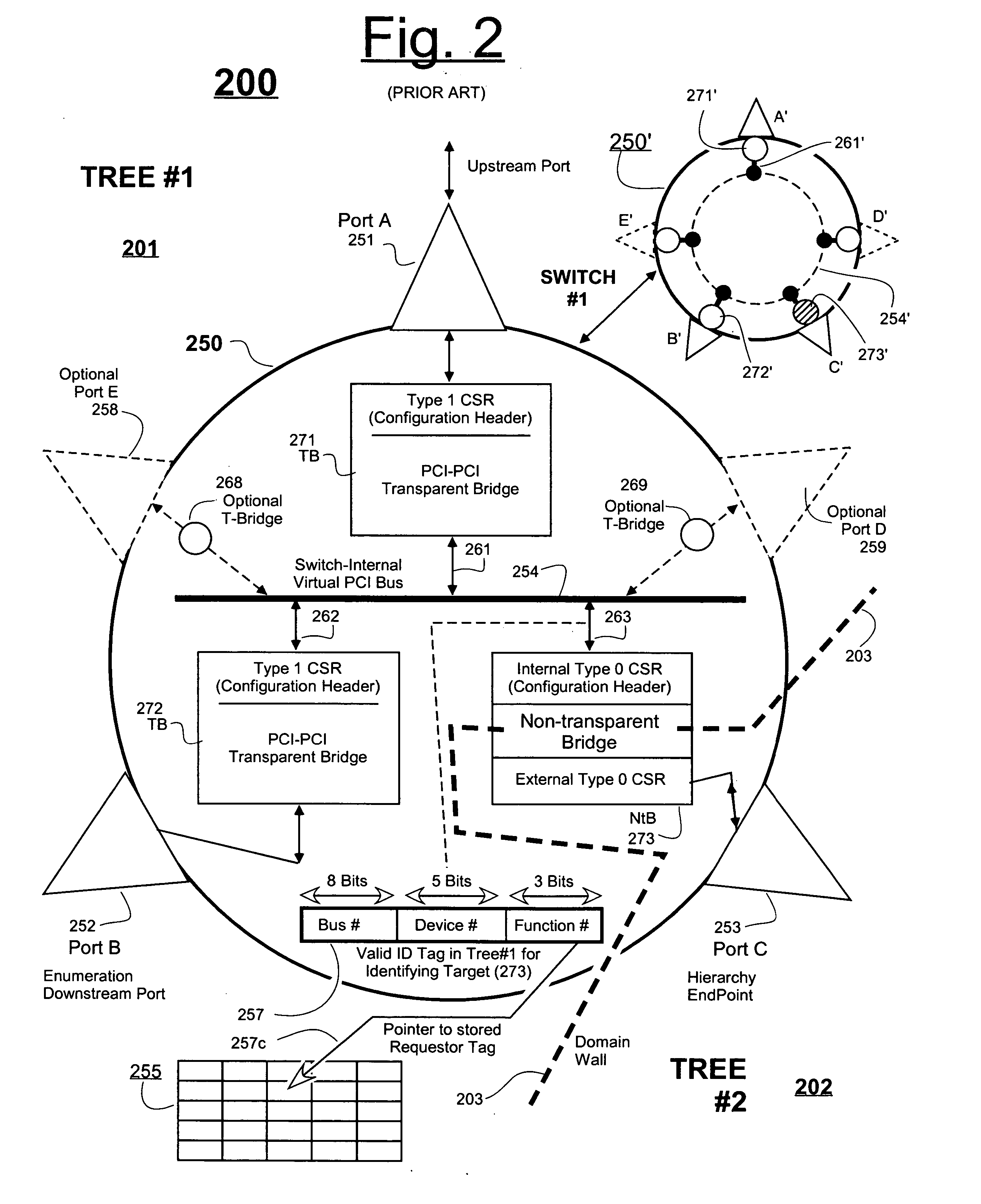
However, the standardized 3-bit size of the Function field in the ID Tag limits the above PLX approach to being able to uniquely pre-designate no more than 23=8 domestic devices as having permission to originate cross-border, split transactions.

Method used


Image

  • Expansion of cross-domain addressing for PCI-express packets passing through non-transparent bridge
  • Expansion of cross-domain addressing for PCI-express packets passing through non-transparent bridge
  • Expansion of cross-domain addressing for PCI-express packets passing through non-transparent bridge

Examples


Embodiment Construction

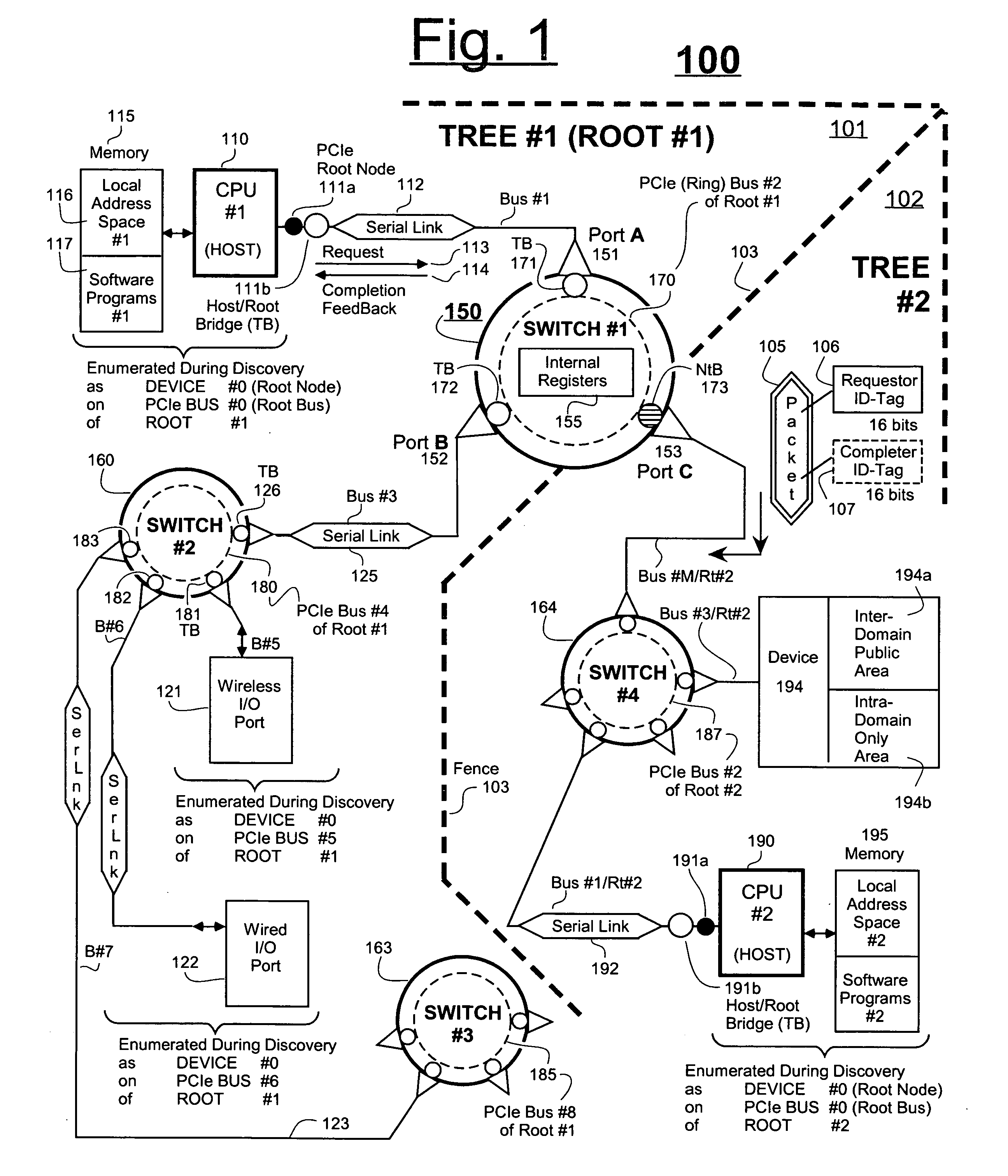
[0024]FIG. 1 is a schematic diagram showing a PCI-Express based communications system 100 comprising a first rooted tree 101 (hereafter also the domestic tree) and a second rooted tree 102 (hereafter also the foreign tree). Dashed boundary line 103 represents a logical border or fence between the two communication trees. Line 103 is also referred to as a domain wall. A non-transparent bridge (NtB 173) straddles the fence 103 between the two trees and thereby allows data exchange between the two trees, 101 and 102.

[0025] Those skilled in the art will quickly recognize from FIG. 1 that CPU 110 (also designated as CPU#1) serves as the root host of tree 101 while CPU 190 (also designated as CPU#2) serves as the root host of tree 102.

[0026] The hosts can be independently powered up or rebooted at various times. When a given host boots up and executes various initialization procedures, one of the procedures it should perform is to investigate the current state of its respective communic...


PUM


Abstract

A PCI-Express compatible switch is provided with two or more, internal virtual buses. In one embodiment, at least one of the plural virtual buses is designated as a special bus that is limited to having no more than 16 devices on it even though the protocol allows for a maximum of 32 devices on each PCI bus. In a supplemental or alternate embodiment, at least one virtual bus is limited to having no devices on it. A non-transparent bridge is provided on at least one of the special buses for providing cross-border routing of packets from one root domain to another root domain. The number-of-devices limitation placed on the special bus reduces the number of bits needed in a corresponding Device identifying field of a destination ID Tag to 4 or less, this integer number being smaller than the prescribed 5 bits called for by the PCI-Express standard for addressing the maximum of 32 devices per bus. As a result, excess bits within the 5-bit Device field are freed for other use. One of the other uses is that of extending beyond 8, the number of domestic devices that can serve as request originators for cross-border split transactions that route through the non-Transparent bridge.

Description

FIELD OF DISCLOSURE [0001] The present invention relates generally to routing of serial packets through networks. The invention relates more specifically to specific types of serial networking protocols where non-posted split transactions take place, such as in PCI-Express and PCI-X. The invention further relates to the use of a special type of bridge, known as a non-Transparent bridge within a PCI-Express or PCI-X network having plural domains. DESCRIPTION OF RELATED ART [0002] The PCI bus is a well known form of standardized signal interchange within the field of digital computer and communication system design. One lesser known extension of the PCI bus standard is referred to as PCI-X. An emerging, but not as yet, well known extension of these is referred to as PCI-Express. The three should not be confused with one another. The present disclosure is mostly directed to the industry-defined, PCI-Express protocol but can also be applied to the older, PCI-X protocol. Both of the latt...

Claims


Application Information

Patent Timeline
Patent Type & Authority Applications(United States)
IPC IPC(8): G06F13/36
CPCG06F13/404Y10S370/912Y10S370/902
Inventor ONUFRYK, PETER Z.REINER, TOM
Owner MICROSEMI STORAGE SOLUTIONS US INC
Learn More