Bicycle wheel driving device

Active Publication Date: 2006-12-21
SHIMANO INC
View PDF4 Cites 14 Cited by
  • Summary
  • Abstract
  • Description
  • Claims
  • Application Information

AI Technical Summary

Benefits of technology

[0010] One object of the present invention is to provide a bicycle wheel driving device configured to drive a

Problems solved by technology

As a result, larger braking forces are needed

Method used


Image

  • Bicycle wheel driving device
  • Bicycle wheel driving device
  • Bicycle wheel driving device

Examples


Embodiment Construction

[0026] Selected embodiments of the present invention will now be explained with reference to the drawings. It will be apparent to those skilled in the art from this disclosure that the following descriptions of the embodiments of the present invention are provided for illustration only and not for the purpose of limiting the invention as defined by the appended claims and their equivalents.

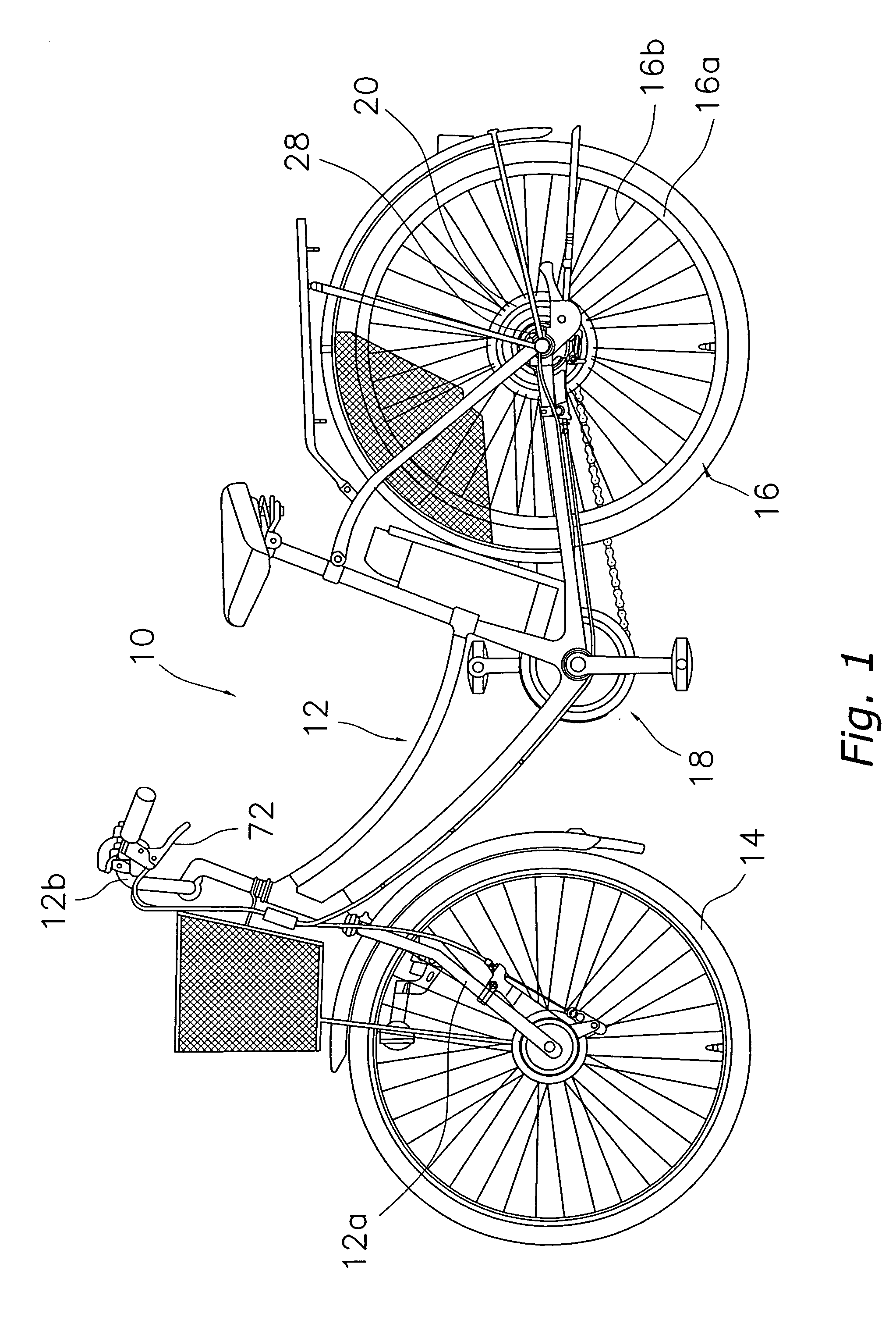
[0027] Referring initially to FIG. 1, a bicycle 10 is illustrated that is equipped in accordance with a first embodiment of the present invention. The bicycle 10 includes among other things a frame 12 with a front fork 12a, a front wheel 14, a rear wheel 16 and a manually powered drive train 18. The front and rear wheels 14 and 16 are arranged on the front and rear of the frame 12 with the manually powered drive train 18 arranged to drive the rear wheel 16 using human power. The manually powered drive train 18 includes one or more front sprockets, one or more rear sprockets, a chain and a crank s...


PUM


Abstract

A motor-equipped hub 20 is provided with a hub axle 22, a hub shell 24, a motor drive unit 26 and a roller brake device 28. The hub shell 24 is arranged around the outside of the hub axle 22, has a hub flange 24a on an outside circumference thereof, and has a housing space 24b on the inside thereof. The motor drive unit 26 is housed inside the housing space 24b and configured to rotate the hub shell 24 with respect to the hub axle 22. The roller brake device 28 is arranged within the hub shell 22 to the outside of the housing space 24b.

Description

CROSS-REFERENCE TO RELATED APPLICATIONS [0001] This application claims priority under 35 U.S.C. § 119 to Japanese Patent Application No. 2005-177232. The entire disclosure of Japanese Patent Application No. 2005-177232 is hereby incorporated herein by reference. BACKGROUND OF THE INVENTION [0002] 1. Field of the Invention [0003] This invention generally relates to a wheel driving device. More particularly, the present invention relates to a bicycle wheel driving device configured to drive a wheel of a bicycle using an electric motor. [0004] 2. Background Information [0005] Bicycling is becoming an increasingly more popular form of recreation as well as a means of transportation. Moreover, bicycling has become a very popular competitive sport for both amateurs and professionals. Whether the bicycle is used for recreation, transportation or competition, the bicycle industry is constantly improving the various components of the bicycle. In recent years, bicycles equipped with a motor o...

Claims


Application Information

Patent Timeline
IPC IPC(8): B62M23/02B62L1/00B62M6/40B62M6/65F16D51/12
CPCB62L1/00Y02T10/705F16D51/10F16D2121/14F16D2125/30B60L11/007B60L11/1805B60L11/1877B60L2200/12B60L2220/44B60L2240/12B60L2240/36B60L2250/24B60L2250/26Y02T10/7005B62M6/60B60L50/20B60L50/52B60L50/66Y02T10/70
Inventor MATSUEDA, KEIJI
Owner SHIMANO INC
Why Eureka
Try Eureka