Clutch actuator

Inactive Publication Date: 2006-12-21
KNORR-BREMSE SYST FUER NUTZFAHRZEUGE GMBH
View PDF9 Cites 32 Cited by
  • Summary
  • Abstract
  • Description
  • Claims
  • Application Information

AI Technical Summary

Benefits of technology

[0008] It is an advantage of the invention that the expensive disengagement lever can be dispensed with by virtue of the fact that the pin is arranged substantially in a plane which is perpendicular with respect to the center axis of the clutch, and is coupled to a rotary element of a gear mechanism which converts its rotational movement into a linear movement of the clutch operator. As the pin, which is present in any case, then replaces the disengagement lever but has to transmit only compressive forces instead of bending moments, it can be dimensioned as previously with a relatively small cross section. The omission of the disengagement lever makes it possible to arrange the clutch actuator, which is flanged onto the outside of the transmission housing of the drive engine in the prior art, at least partially within the housing. As a result, the installation space which is required is reduced advantageously.
[0009] Furthermore, substantially greater force transmission ratios can be realized by gear mechanisms which convert rotational movements into linear movements, such as spindle mechanisms or disks having intermeshing ramp-shaped toothing systems, than by the disengagement lever of the prior art. As a consequence, the clutch actuator has to apply lower actuation forces, which in turn makes a smaller clutch actuator possible. Moreover, gear mechanisms of this type have a very small

Problems solved by technology

The disengagement lever is loaded with high forces and bending moments, for which reason it has large dimensions and is usually configured as a forging, which in turn causes relatively high manufacturing costs.
Moreover, the disengagement lever offers only a low force transmission ratio, with the result that the clutch actuator has to be of correspondingly large dimensions.
It is disadvantageous here, however, that a relative

Method used


Image

  • Clutch actuator
  • Clutch actuator
  • Clutch actuator

Examples


Example

DETAILED DESCRIPTION OF THE DRAWINGS

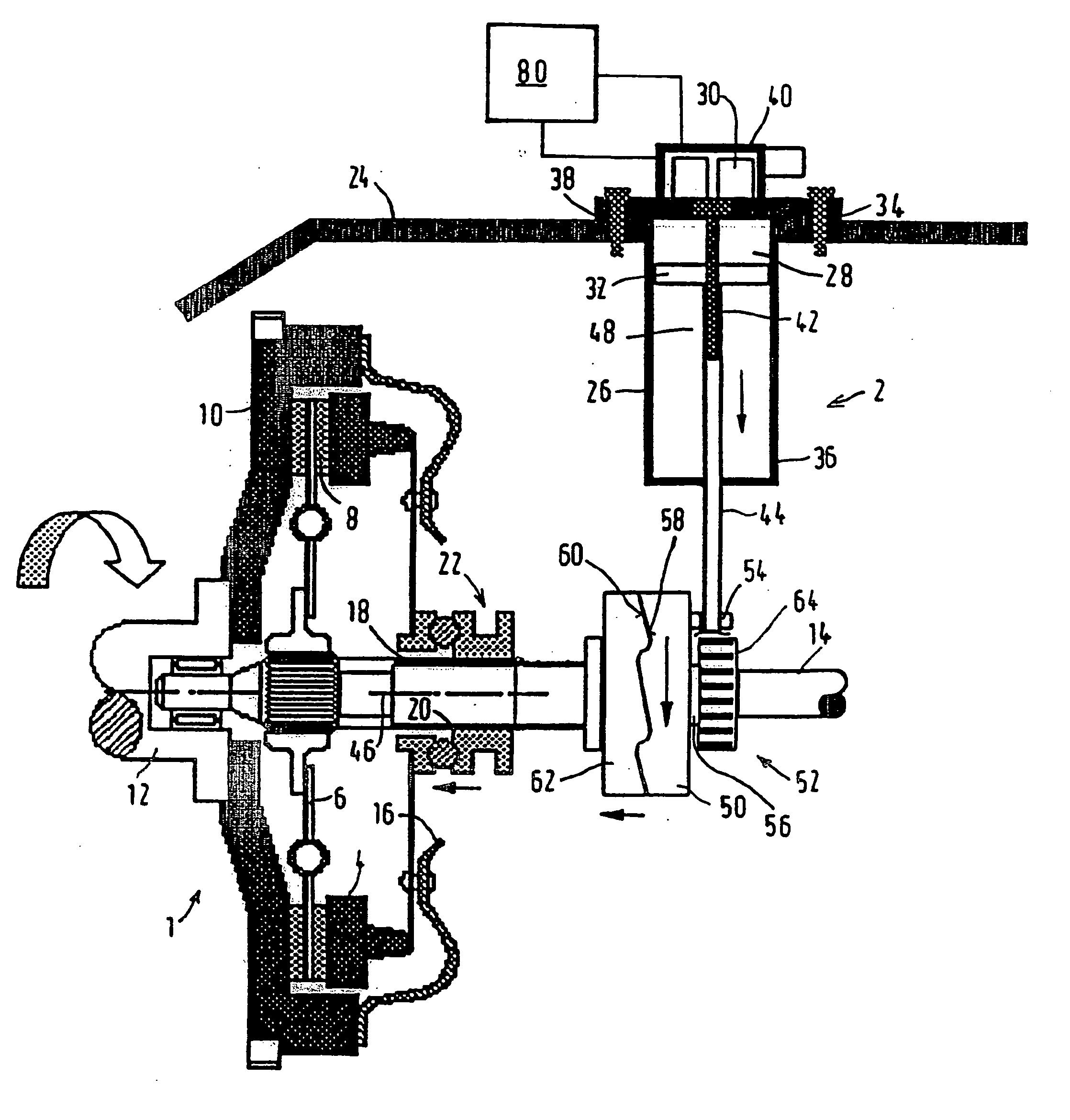
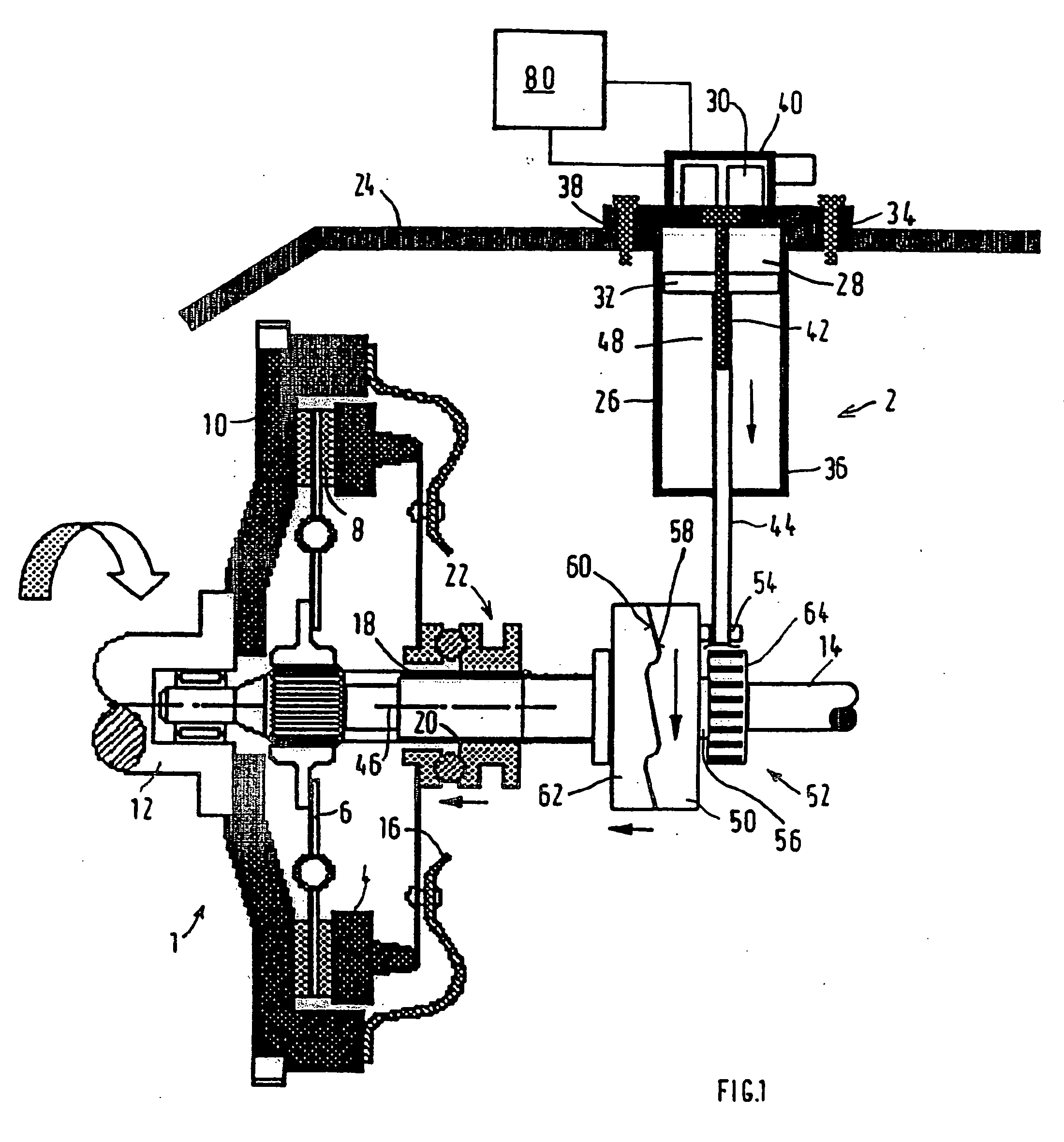
[0032] The friction clutch, which is shown in FIG. 1 and is denoted overall by the designation 1, of a commercial vehicle between a drive engine and a transmission is preferably a single-disk dry clutch, which is actuated by a clutch actuator 2 according to the invention in accordance with a first embodiment.

[0033] The friction clutch 1 includes a pressure plate 4, a clutch plate 6 to which two friction linings 8 are adhesively bonded or riveted, and a further friction surface which is formed by an engine flywheel 10. The engine flywheel 10 and the pressure plate 4 are connected to an output shaft 12 of the drive engine, and the clutch plate 6 is connected to a transmission input shaft 14. For force transmission when the friction clutch 1 is closed, a disk spring 16 clamps the clutch plate 6 between the pressure plate 4 and the engine flywheel 10. In order to open the friction clutch 1, for example for a gear change operation, a disengagement be...


PUM


Abstract

A clutch actuator is provided for operating a clutch between a drive motor and a gearbox on a motor vehicle, in particular a commercial vehicle, including a linearly operating pin, acting on a release mechanism which is coaxial to a mid-axis of the clutch. The pin is arranged in a plane essentially perpendicular to the mid-axis of the clutch and coupled eccentrically to a rotating body of a gear mechanism, converting the rotating movement thereof into a linear movement of the release mechanism.

Description

CROSS REFERENCE TO RELATED APPLICATIONS [0001] This application is a Continuation of PCT Application No. PCT / EP2004 / 007706, filed on Jul. 13, 2004, which claims priority of German Application No. 103 31 927.1, filed Jul. 15, 2003, the disclosure of which is expressly incorporated by reference herein.BACKGROUND AND SUMMARY OF THE INVENTION [0002] The invention relates to a clutch actuator for actuating a clutch between a drive engine and a transmission of a motor vehicle, in particular a commercial vehicle, including a linearly actuable pin which acts on a release mechanism which is coaxial with respect to a center axis of the clutch. [0003] A clutch actuator of this type is known, for example, from DE 100 14 225 A1. A clutch actuator of this type is usually flanged onto the outside of the transmission housing and has a linearly actuated pin, which is arranged parallel to the center axis of the clutch and is coupled to one end of a disengagement lever which is mounted pivotably withi...

Claims


Application Information

Patent Timeline
IPC IPC(8): F16D13/75F16D25/08
CPCF16D13/755F16D2023/123F16D13/757
Inventor MILLER, BERNHARD
Owner KNORR-BREMSE SYST FUER NUTZFAHRZEUGE GMBH
Why Eureka
Try Eureka