Centrifugal drum clutch assembly and method of manufacture

a technology of centrifugal drum and clutch assembly, which is applied in the direction of rigid shaft couplings, mechanical devices, couplings, etc., can solve the problems of limited torque transfer from the clutch drum to the drive means, unfavorable and unfavorable aspects, and use of less expensive materials, so as to achieve cost savings and increase production output

Inactive Publication Date: 2006-12-21
BEERENS THOMAS
View PDF6 Cites 3 Cited by
  • Summary
  • Abstract
  • Description
  • Claims
  • Application Information

AI Technical Summary

Benefits of technology

[0011] According to an object of the present invention there is provided a clutch drum assembly comprising a clutch drum and drive means, wherein the assembly of the two components has been streamlined resulting in significant cost savings and increased production output.
[0012] According to another object of the present invention there is provided a clutch drum assembly comprising a clutch drum and drive means wherein the design of the individual components has been simplified in such a manner as to reduce their manufacturing cost and facilitate the said streamlined assembly.
[0013] Yet another object of the present invention is to provide the said efficiencies and said cost savings without sacrificing any of the said robust and reliability requirements.

Problems solved by technology

The broad use of clutch drum assemblies in various sizes and configurations depending on application has resulted in a diverse number of approaches to the manufacture of the clutch drum assemblies and associated costs, each approach having favorable and unfavorable aspects.
The method used to couple the clutch drum and drive means is critical as the amount of torque that may be transferred from the clutch drum to the drive means is limited by the quality and strength of the connection.
This improved product is cheaper to produce however the use of less expensive materials for the clutch drum and drive means may be unreliable in larger devices requiring significantly higher torque output; furthermore the device is not adaptable to arrangements where a drive spline or sprocket is required.
This improved device has very high torsion and lateral strength however, the manufacturing process involves several steps and consequently is a relatively expensive clutch drum and drive means assembly to manufacture in comparison to previously more inferior assemblies that may not be as reliable or have equivalent torsion strength.
Other prior disclosures utilise variations on the above arrangements in an attempt to address the stated requirements however none appear to be able to achieve the objectives in a truly efficient and cost effective manner while being universally applicable to this type of connection between a clutch drum and drive means.

Method used


Image

  • Centrifugal drum clutch assembly and method of manufacture
  • Centrifugal drum clutch assembly and method of manufacture
  • Centrifugal drum clutch assembly and method of manufacture

Examples


Embodiment Construction

[0025] A particularly preferred embodiment of the invention and method for assembly will now be discussed with reference to FIGS. 1 to 6.

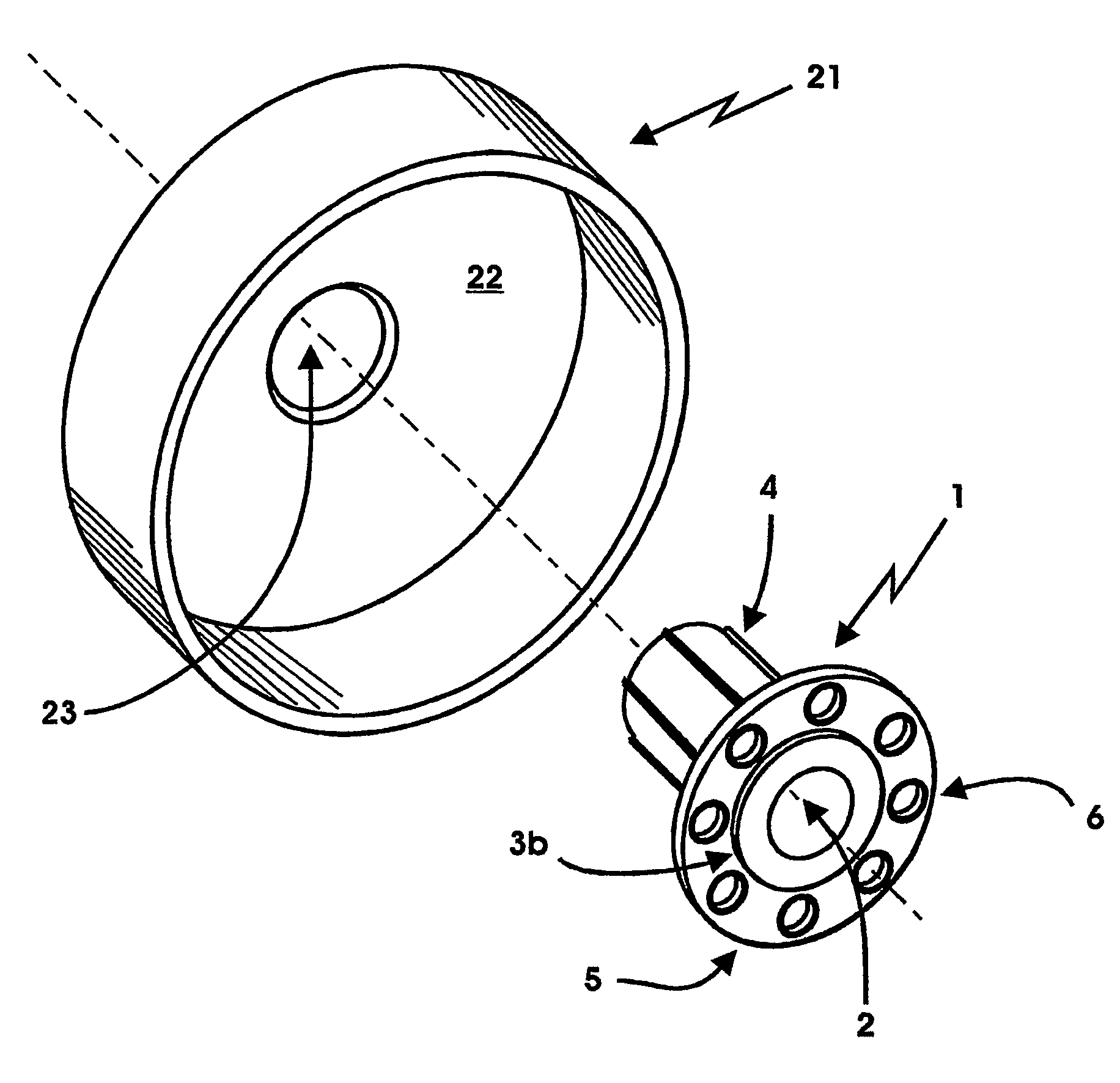
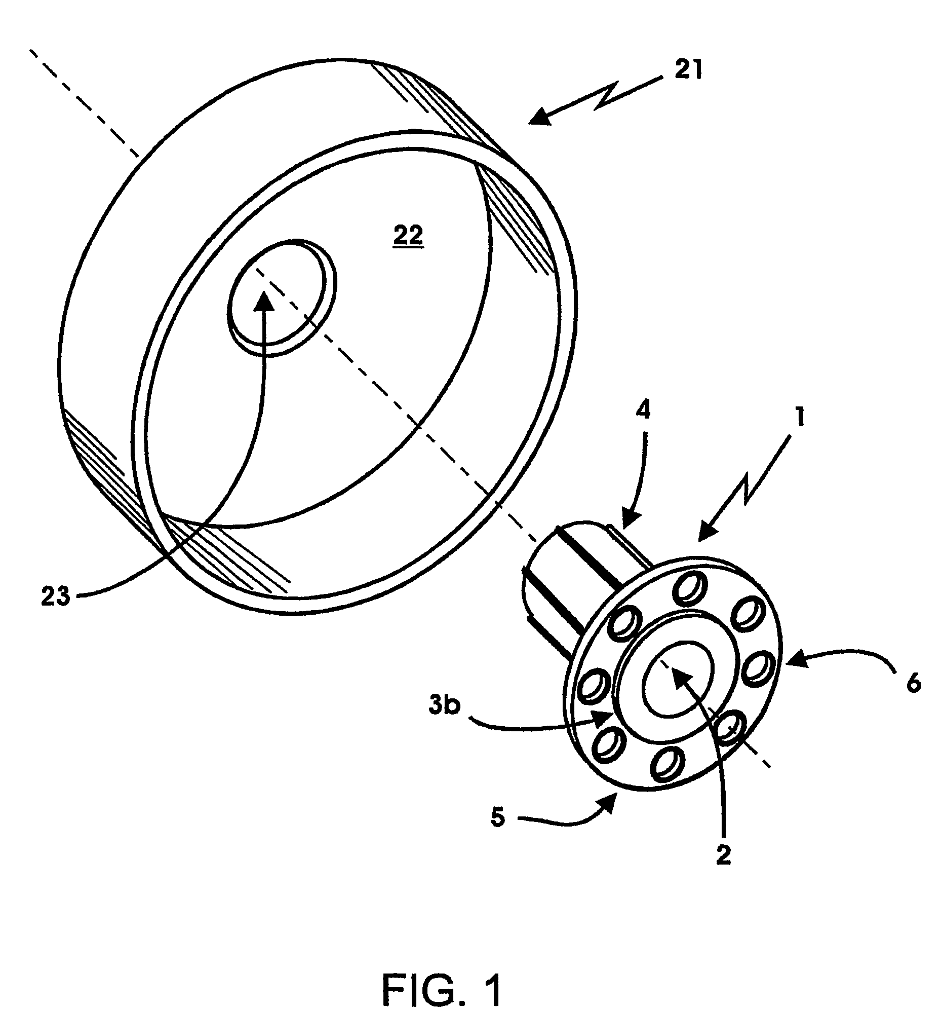
[0026] In FIG. 1 is provided a drive spline 1 with a through bore 2, a rear spigot 3b, an axial splined extension 4 and a flange 5. Said flange 5 is provided with one or more substantially similar and minimally sized apertures 6 that are counter sunk or counter bored to the side opposite the axial splined extension 4 and are reasonably evenly located radially around the flange 5. A clutch drum 21 has an end wall 22 and a centrally located aperture 23.

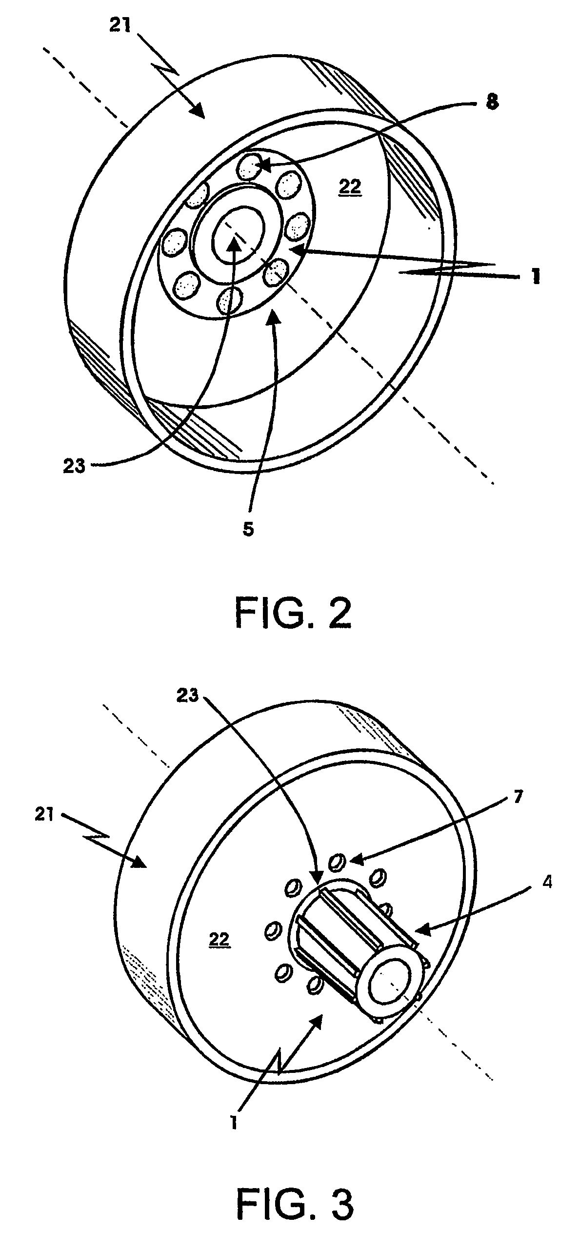
[0027] When assembled the clutch drum assembly, FIG. 2 and FIG. 3, show the axial splined extension 4 of the drive spline 1 inserted through the centrally located aperture 23 of the end wall 22 of the clutch drum 21. Metal depressions 7 created in the exterior end wall 22 of the clutch drum 21 in line with the minimally sized apertures 6 in the flange 5 project through the minimally sized apertures 6...


PUM


Abstract

A clutch drum assembly comprising a clutch drum (21) and a drive means. The clutch drum (21) has an axis of rotation and includes an end wall (22). The drive means specifically a drive spline (1) or a fixed drive sprocket axially to one end of drive means, is a flange (5) with one or more radial evenly spaced minimally sized apertures (6) that have been counter sunk or counter bored to one side. Unitary axial motion of the two components is achieved via a mechanical connection between the two said components by tightly pressing metal from the outer surface of the end wall (22) clutch through each of the minimally sized apertures (6) in the drive means flange (5) against a die positioned proximate to each said aperture (6) forging the metal into the counter sunk or counter bored portion of the drive means flange (5).

Description

FIELD OF THE INVENTION [0001] This invention generally relates to centrifugal clutches and more particularly to improvements in the method by which the drive means is permanently fixed to the clutch drum. BACKGROUND OF THE INVENTION [0002] Drive devices such as centrifugal clutches are widely used to transmit torque from an engine or motor to a user device. The centrifugal clutch art in this respect is well developed with centrifugal clutch devices being used in smaller vehicles like go karts and motor bikes and tools like chainsaws, brush cutters and flexible cable grass cutters. [0003] This invention relates to drive device assemblies that include a clutch drum and one of various drive means that may be coupled to the clutch drum including a fixed drive sprocket, a drive spline or a drive shaft; where a fixed drive sprocket directly drives a user device; a drive spline drives a user device indirectly with the addition of a replaceable drive sprocket; and a drive shaft drives a use...

Claims


Application Information

Patent Timeline
Patent Type & Authority Applications(United States)
IPC IPC(8): F16D13/62F16D43/18
CPCF16D1/072F16D1/076F16D13/62F16D2065/1392F16D65/10F16D2065/1388F16D43/18
Inventor BEERENS, THOMAS
Owner BEERENS THOMAS
Why Eureka
Try Eureka