Ceramic-metal assembly and ceramic heater

Inactive Publication Date: 2006-12-21
NGK SPARK PLUG CO LTD
View PDF8 Cites 10 Cited by
  • Summary
  • Abstract
  • Description
  • Claims
  • Application Information

AI Technical Summary

Benefits of technology

[0010] In view of the above, an object of the present invention is to provide a ceramic-metal assembly and a ceramic heater in which high adhesion between an electrode pad and connecti

Problems solved by technology

If the ceramic content is lower than 20 vol %,

Method used


Image

  • Ceramic-metal assembly and ceramic heater
  • Ceramic-metal assembly and ceramic heater
  • Ceramic-metal assembly and ceramic heater

Examples


example 1

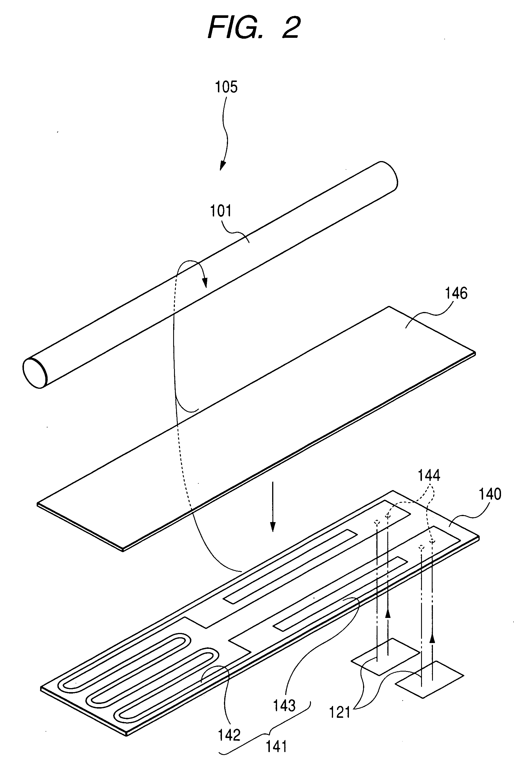
[0047] A slurry was produced by mixing material powders of alumina (93 wt %) and a sintering aid (7 wt %), and a 0.3-mm-thick flat plate was formed from this slurry by a doctor blade method. A plate-like green sheet 140 of 60 mm in length and 10 mm in width was produced by punching the flat plate. Four through-holes 144 for electrical connection to electrode pads 121 were formed in the green sheet 140, and a heating resistor 141 was printed on one surface of the green sheet 140 by applying a metal paste mainly made of tungsten from around the four through-holes. The metal paste was also charged into the through-holes 144 to secure electrical continuity.

[0048] Then, two two-layer electrode pads 121 were formed on the other surface of the green sheet 140 by pattern printing with a metal paste that was prepared separately for each sample. Each electrode pad 121 measured approximately 2.5 mm×5 mm. A green sheet 146 made of the same material as the green sheet 140 was laminated on that ...


PUM


Abstract

A ceramic-metal assembly including: a ceramic base; an electrode pad provided on a surface of the ceramic base; a connection terminal for external electrical connection; and a joining portion which joins the connection terminal to the electrode pad. The electrode pad has a first layer which is in contact with the ceramic base and a second layer which is in contact with the joining portion. The first layer contains 20 to 50 vol % of a ceramic component, and the second layer contains a component of the joining portion.

Description

BACKGROUND OF THE INVENTION [0001] 1. Field of the Invention [0002] The present invention relates to a ceramic-metal assembly and a ceramic heater. More specifically, the invention relates to a ceramic heater including an electrode pad of a ceramic-metal assembly having increased adhesion to its ceramic base and a connection terminal. [0003] 2. Description of the Related Art [0004] Conventionally, ceramic heaters in which a heating resistor made of a refractory metal such as tungsten or molybdenum is buried in a ceramic base made of alumina or the like are widely used. For example, a ceramic heater that is inserted in a sensor element of a gas sensor is formed by winding a ceramic green sheet incorporating a heating resistor around a ceramic porcelain tube and firing the resulting assembly to form an integral body. The ceramic beater, on its outer circumferential surface, also has electrode pads that are electrically connected to the heating resistor. Also, connection terminals for ...

Claims


Application Information

Patent Timeline
IPC IPC(8): H05B3/68
CPCH05B3/141H05B3/12
Inventor SAKURAI, KIKUOTAKAGI, YASUHIROTANAKA, KUNIHARUSUZUKI, MASAHITO
Owner NGK SPARK PLUG CO LTD
Why Eureka
Try Eureka