
Material processing system and method

a material processing and material technology, applied in the field of material processing systems, can solve the problems of unsatisfactory accuracy with which the processing of work pieces may be carried out in the conventional system, and achieve the effects of high vacuum, higher gas pressure, and higher gas pressur

Inactive Publication Date: 2006-12-21
CARL ZEISS SMT GMBH +1
View PDF46 Cites 32 Cited by
  • Summary
  • Abstract
  • Description
  • Claims
  • Application Information

AI Technical Summary

Benefits of technology

[0008] Accordingly, it is an object of the present invention to provide a material processing system, a material processing method and a gas supply arrangement applicable for such purposes which allow to process the work piece to be processed with higher precision.
[0044] Preferably, this end face is spaced apart from the object plane by a distance of less than 100 μm, preferably less than 50 μm. This allows to separate the subsection sufficiently from the rest of the processing chamber without contact being established between the end face and the work piece to be processed. As a result, increased pressures of the at least one reactive gas can be generated within the subsection.

Problems solved by technology

The conventional system was found to be unsatisfactory as regards the accuracy with which the processing of the work pieces may be carried out.

Method used


Image

  • Material processing system and method
  • Material processing system and method
  • Material processing system and method

Examples


Embodiment Construction

[0060] In the exemplary embodiments described below, components that are alike in function and structure are designated as far as possible by alike reference numerals. Therefore, to understand the features of the individual components of a specific embodiment, the descriptions of other embodiments and of the summary of the invention should be referred to.

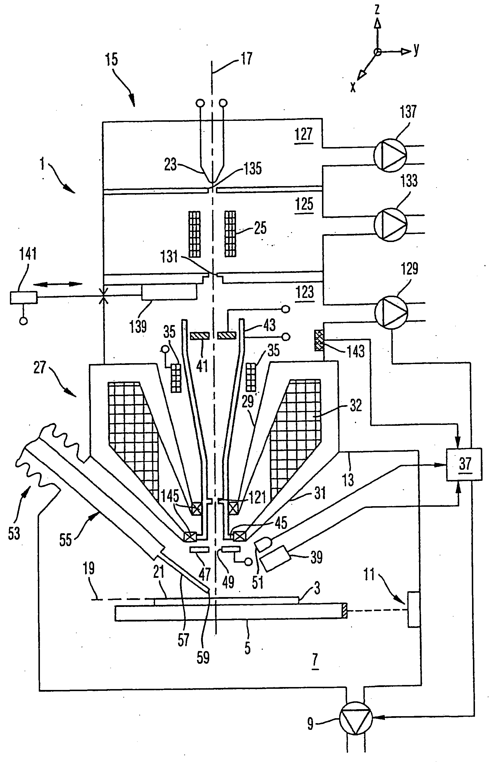
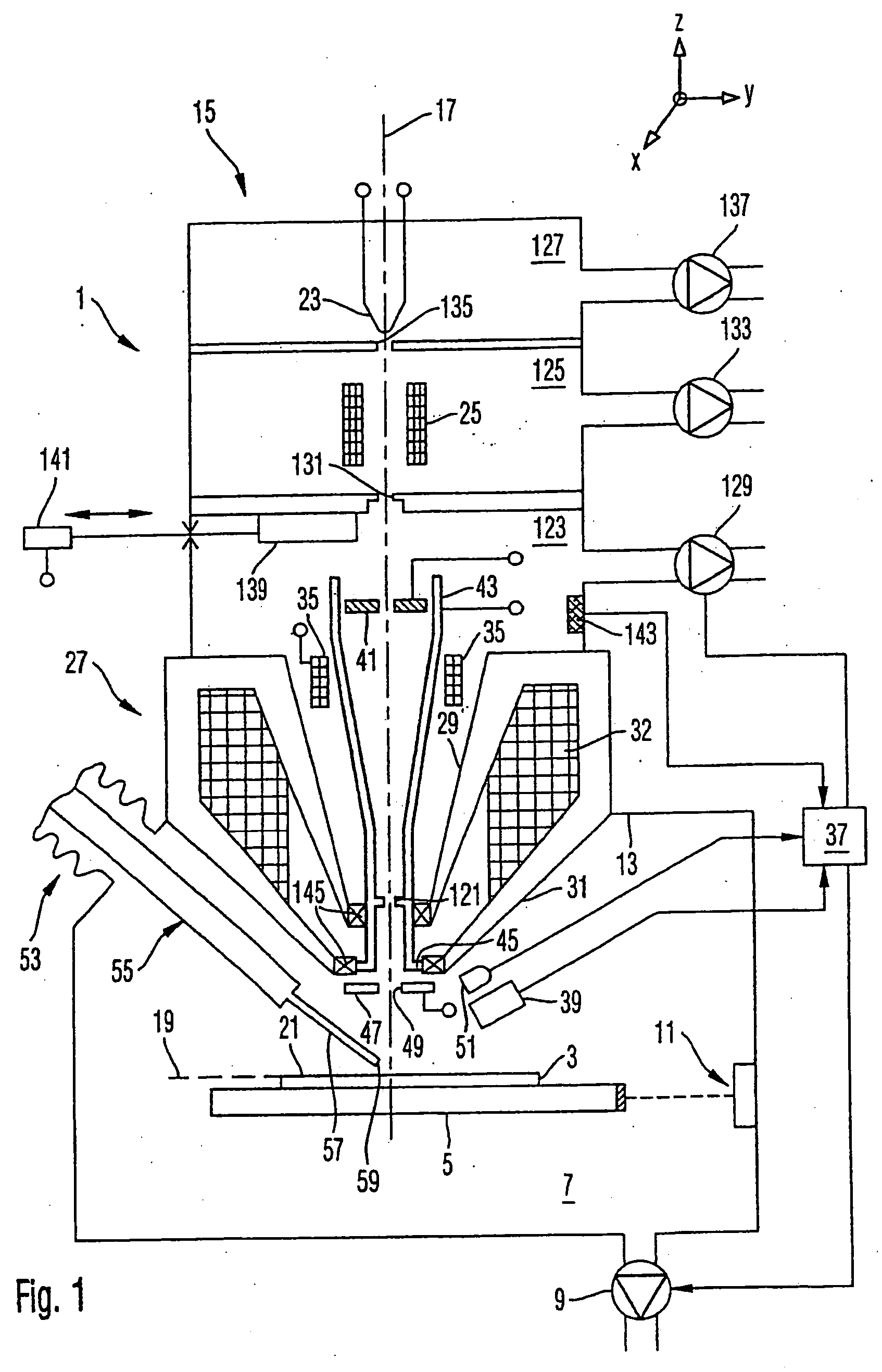
[0061]FIG. 1 schematically illustrates an embodiment of a material processing system 1 according to the invention. This system is used to process a work piece 3, namely a phase mask. This photo mask serves for use in a photolithographic process and carries structures which are photographically transferred to a radiation-sensitive layer (resist) with which a semiconductor substrate (wafer) is coated. In relation to the wavelength of the light used to transfer the structures from the mask to the semiconductor substrate, the critical dimensions of the structures are relatively small. Therefore, the structures on the mask are not merel...


PUM

PropertyMeasurementUnit
outer diameteraaaaaaaaaa

Abstract

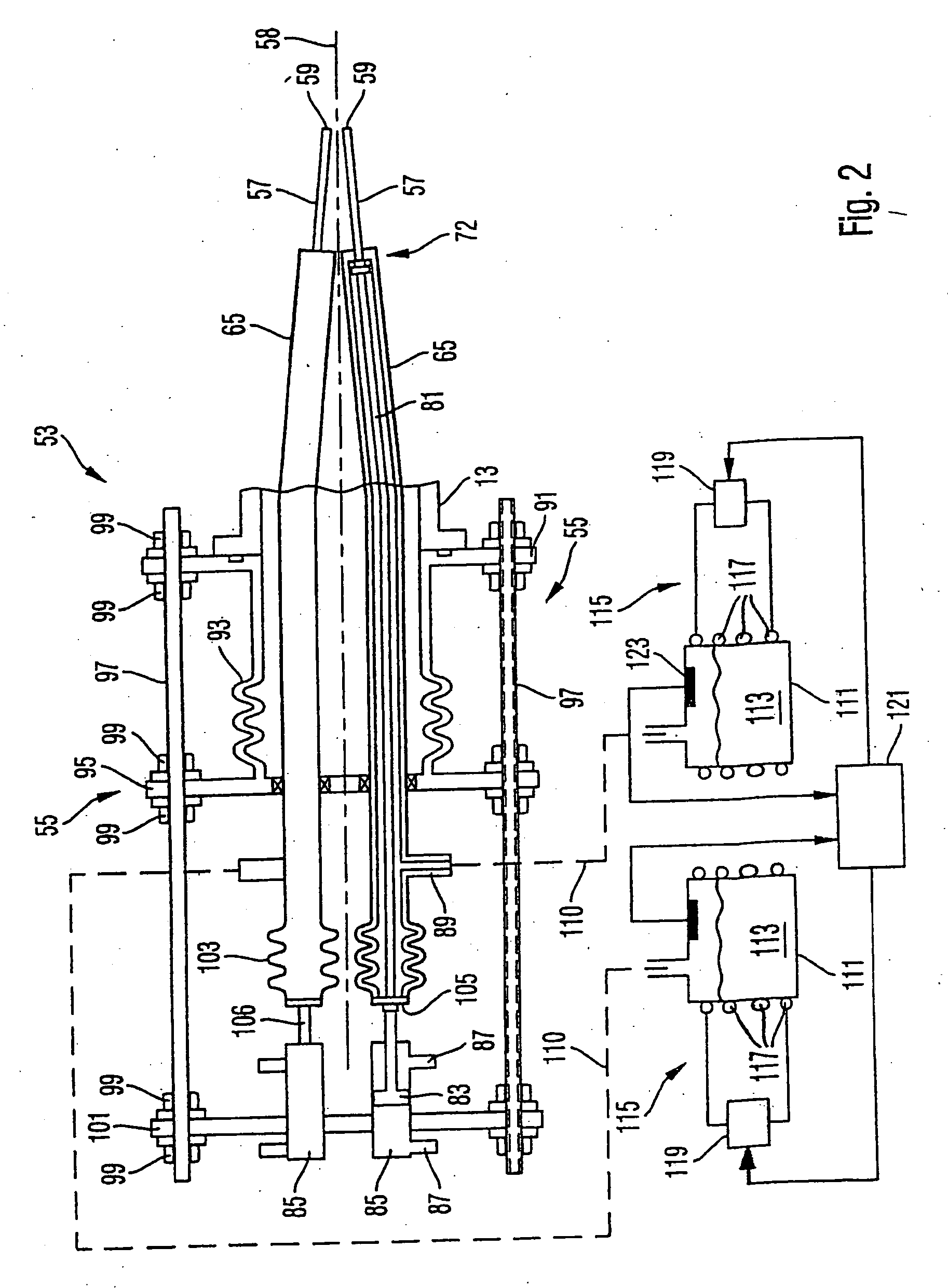
A material processing system for processing a work piece is provided. The material processing is effected by supplying a reactive gas and energetic radiation for activation of the reactive gas to a surrounding of a location of the work piece to be processed. The radiation is preferably provided by an electron microscope. An objective lens of the electron microscope is preferably disposed between a detector of the electron microscope and the work piece. A gas supply arrangement of the material processing system comprises a valve disposed spaced apart from the processing location, a gas volume between the valve and a location of emergence of the reaction gas being small. The gas supply arrangement further comprises a temperature-adjusted, especially cooled reservoir for accommodating a starting material for the reactive gas.

Description

[0001] This application is a divisional of copending U.S. patent application Ser. No. 10 / 923,814 filed Aug. 24, 2004, which is a continuation of International Application No. PCT / EP03 / 01923 filed on Feb. 25, 2003, which International Application was published by the International Bureau on Aug. 28, 2003, and which was not published in English. This application also claims the benefit of DE 102 08 043.7 filed on Feb. 25, 2002. The entire contents of each of the above-identified applications are incorporated herein by reference.BACKGROUND OF THE INVENTION [0002] 1. Field of the Invention [0003] The invention relates to a material processing system, a material processing method and a gas supply arrangement for the same, especially for use in methods for processing materials by material deposition from gases, such as CVD (Chemical Vapor Deposition), or material removal involving supply of reactive gases. In particular, the gas reaction resulting in a material deposition or a material re...

Claims


Application Information

Patent Timeline
Patent Type & Authority Applications(United States)
IPC IPC(8): G21K7/00C23C16/00
CPCH01J37/3056H01J2237/006H01J2237/31744H01J2237/166H01J2237/31732H01J2237/162
Inventor KOOPS, HANS W.P.HOFFROGGE, PETER
Owner CARL ZEISS SMT GMBH
Learn More