
Cathode ray tube

Inactive Publication Date: 2006-12-21
MATSUSHITA TOSHIBA PICTURE DISPLAY CO LTD
View PDF2 Cites 2 Cited by
  • Summary
  • Abstract
  • Description
  • Claims
  • Application Information

AI Technical Summary

Benefits of technology

[0009] It is an object of the present invention to solve the conventional problems described above and to provide a cathode ray tube that includes a panel having a substantially flat useful portion, is easy to manufacture and allows the reduction of the weight and cost of the panel.

Problems solved by technology

Thus, especially in the envelope 10 for middle and large sized tubes such as at least about 51-cm-diagonal tubes, the vicinity of the frit glass 8 (namely, a sealing portion) is likely to be cracked, so that the manufacturing is not easy.
This problem is more serious for the envelope using the panel 3 whose useful portion has a substantially flat outer surface, which has become widespread recently.
However, the former method has the following problem.
That is, the plastic reinforcer 7 that withstands a high temperature is expensive.
Also, when the exhausting process is carried out at a low temperature, it takes a very long time to achieve the necessary degree of vacuum.
Thus, an excellent cathode ray tube cannot be manufactured.
On the other hand, the latter method has the following problem.

Method used


Image

  • Cathode ray tube
  • Cathode ray tube
  • Cathode ray tube

Examples


Embodiment Construction

[0022] Conventionally, since a larger stress has been generated in a long side than in a short side in the sealing portion of the panel in the exhausting process, the long side has been likely to be cracked. In contrast, the panel according to the present invention satisfies Formulae (1) and (2), whereby the stress generated in the short side and that generated in the long side in the sealing portion in the exhausting process are substantially equalized. As a result, the stress generated in the long side lowers, so that it is possible to withstand the stress in the exhausting process sufficiently even when the panel is made thinner than a conventional panel. In other words, it is possible to achieve a cathode ray tube that has a thin panel, is not cracked easily and is easy to manufacture.

[0023] Further, the reduction of the panel thickness achieves a lighter panel and a lower material cost. Moreover, it becomes possible to shorten the time for the exhausting process and reduce the...


PUM


Abstract

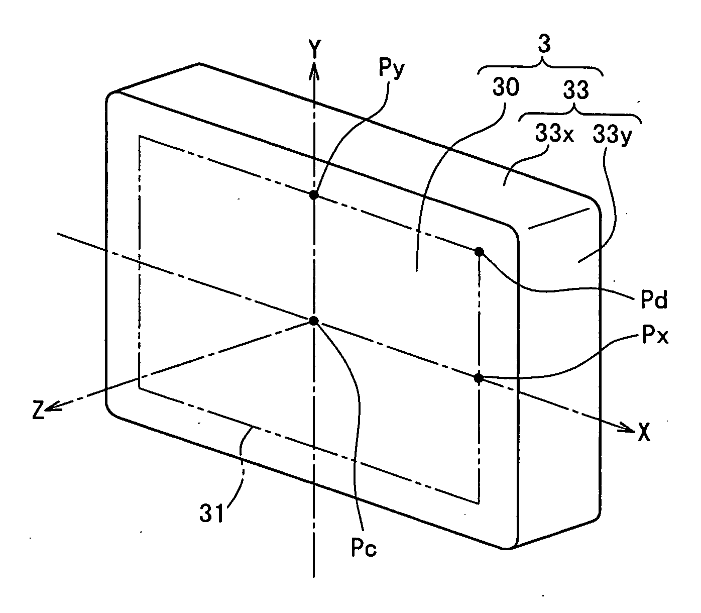
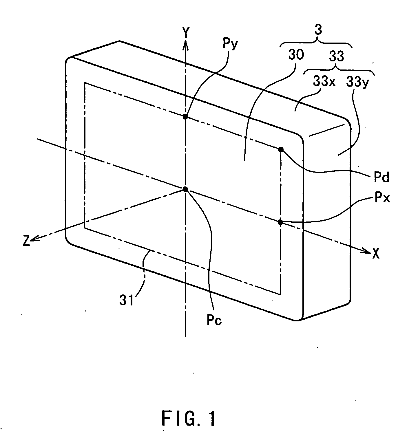
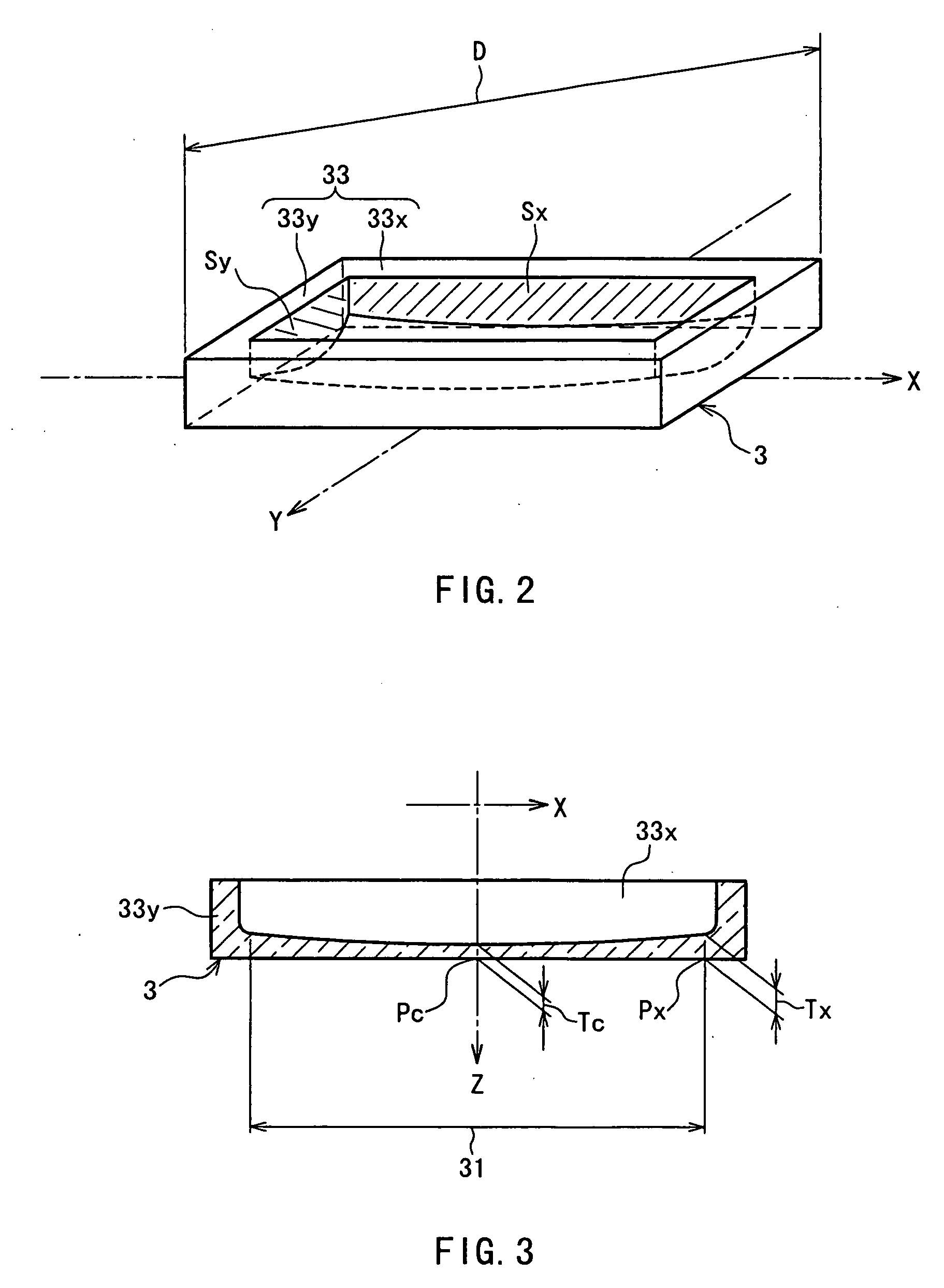
When the thickness of the panel at an X axis end of the useful portion is expressed by Tx (mm), the thickness thereof at a Y axis end is expressed by Ty (mm), the thickness thereof at the center is expressed by Tc (mm) and an outer dimension of the panel along the diagonal axis direction is expressed by D (mm), 0.8≦(100×Tc / D)2×(Tx / Ty)≦2.2 and 0.012≦Tc / D≦0.019 are satisfied. Accordingly, the stress generated in a short side and that generated in a long side in a sealing portion in an exhausting process are substantially equalized. As a result, cracking of the panel can be reduced in the exhausting process even when the panel is made thinner. Therefore, it is possible to provide a cathode ray tube that is easy to manufacture and has a lighter and less expensive panel.

Description

BACKGROUND OF THE INVENTION [0001] 1. Field of the Invention [0002] The present invention relates to a cathode ray tube. [0003] 2. Description of Related Art [0004] As shown in FIG. 9, a cathode ray tube 1 used in a television receiver or the like includes an envelope 10 constituted by a glass panel 3 whose inner surface is provided with a phosphor 2 or the like and a glass funnel 5 whose inner surface is provided with an electrically conductive film 4 or the like that are sealed with a frit glass 8. An electron beam emitted from an electron gun 6 disposed in a neck portion 5a of the funnel 5 strikes the phosphor 2 so as to emit light, thereby displaying an image. [0005] A process of manufacturing such a cathode ray tube 1 includes a sealing process of passing the panel 3 and the funnel 5 through a furnace at about 450° C. for sealing them with the frit glass 8 and an exhausting process of passing the cathode ray tube 1 through a furnace at about 350° C. for exhausting the cathode r...

Claims


Application Information

Patent Timeline
IPC IPC(8): H01J29/86H01J29/92H01J29/88H01J29/87
CPCH01J9/244H01J29/87H01J29/86
Inventor KAWASAKI, MASAKIYAMASHITA, HIROYUKIYAMAUCHI, MASAHIDEIGUCHI, HIDEOKAWANO, MASAHARUKAWAMOTO, AKEMI
Owner MATSUSHITA TOSHIBA PICTURE DISPLAY CO LTD
Learn More