
Image data distribution control method, device, system and program

a distribution control and image technology, applied in the direction of digital output to print units, television systems, instruments, etc., can solve the problems of not becoming a substantial solution, complicated processing, and traffic on the network to increase even further, so as to improve the reliability of the distribution of moving images, increase the consumption power, and increase the network traffic

Inactive Publication Date: 2006-12-21
RAKUTEN INC
View PDF24 Cites 21 Cited by
  • Summary
  • Abstract
  • Description
  • Claims
  • Application Information

AI Technical Summary

Benefits of technology

[0014] Taking the aforementioned circumstances into consideration, it is a first object of the present invention to provide a method, device, system and computer program that make it possible in the distribution of moving images to optimize the quality of distributed images according to the reception environment of the recipient, while at the same time keeping increase of traffic to a minimum.
[0060] Also, with this invention, since it is possible to obtain the two aforementioned effects, it is possible to keep any increase in consumption power required by the reception device to a minimum.

Problems solved by technology

However, in the prior methods of using a re-transmission request to supplement data loss when packet loss occurs, the re-transmission request information and re-transmitted data cause the traffic on the network to increase even further.
Therefore, this does not become a substantial solution when packets are lost due to congested traffic.
Moreover, complicated processing is required in order to control the power of the wireless transmission path of each recipient.
Furthermore, there are cases in which packet loss occurs even though a method for performing re-transmission control or power control of the wireless transmission path of each recipient is employed.
However, even in this error concealment method it is not possible to remove disturbance in the decoded image.
Also, since inter frame prediction is used, there is a problem in that disturbance in an image that has once been generated also propagates to the following frames.

Method used


Image

  • Image data distribution control method, device, system and program
  • Image data distribution control method, device, system and program
  • Image data distribution control method, device, system and program

Examples


first embodiment

[0074] In a first embodiment of the invention, an image data distribution device comprises: means for distributing a plurality of moving mage data (for example, moving image data having differing degrees of image quality) for the same image in different sessions; and means for setting routing priority control for the transmission path, or power control for a wireless transmission path for each session for distributing the moving image data. An image data reception device comprises: means for receiving data distributed in at least one session, and means for selecting data from among the received moving image data based on image quality, and then reconstructing and decoding that data into single moving image data.

[0075] Furthermore, in the first embodiment of the invention, the image data reception device can also be constructed such that it comprises means for selecting whether or not to receive at least one session based on at least one of the error / loss ratio of received data, the...

example 1

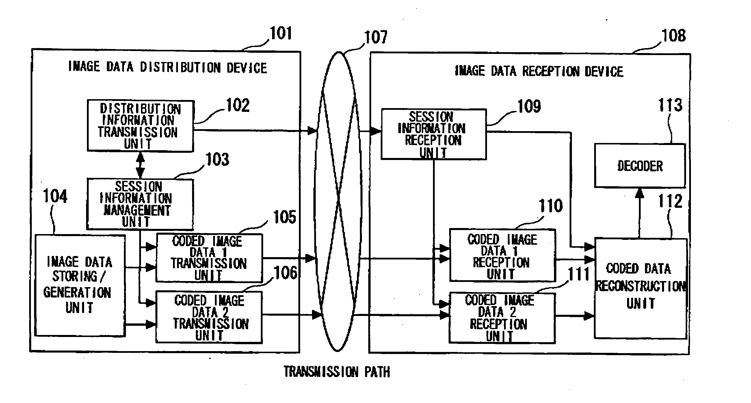
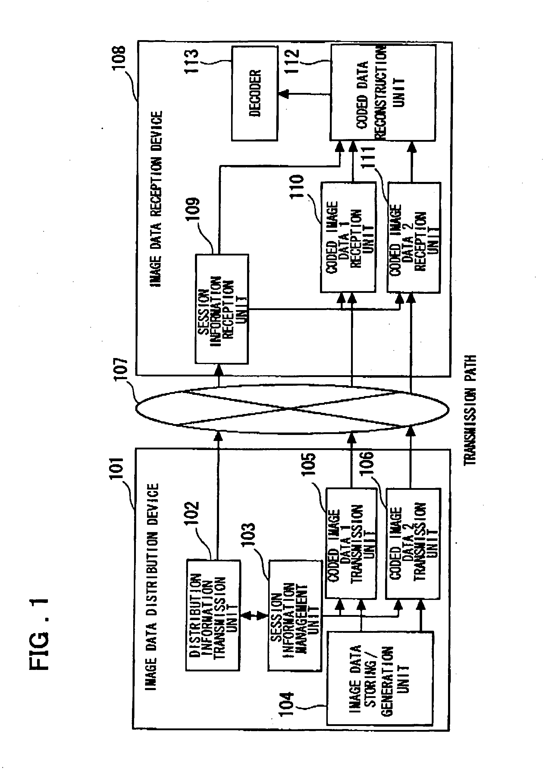
[0076] The first example of the present invention will be explained with reference to the drawings. FIG. 1 shows the construction of this first example of the invention. As shown in FIG. 1, this example comprises: an image data distribution device 101 that distributes coded image data, an image data reception device 108, and a transmission path 107 for transmitting the coded image data. In this example, the image data distribution device 101 is connected to the transmission path 107, which is an IP (Internet Protocol) network, and it uses UDP (User Datagram Protocol) / IP to distribute the coded image data. The image data reception device 108 is presumed to be a client terminal that is connected to the IP network. In this example, in order to simplify the explanation, the number of image data to be distributed will be explained as being two, however, of course, in this invention, the number of image data to be distributed is not limited to two.

[0077] The image data distribution devic...

second embodiment

of the Invention

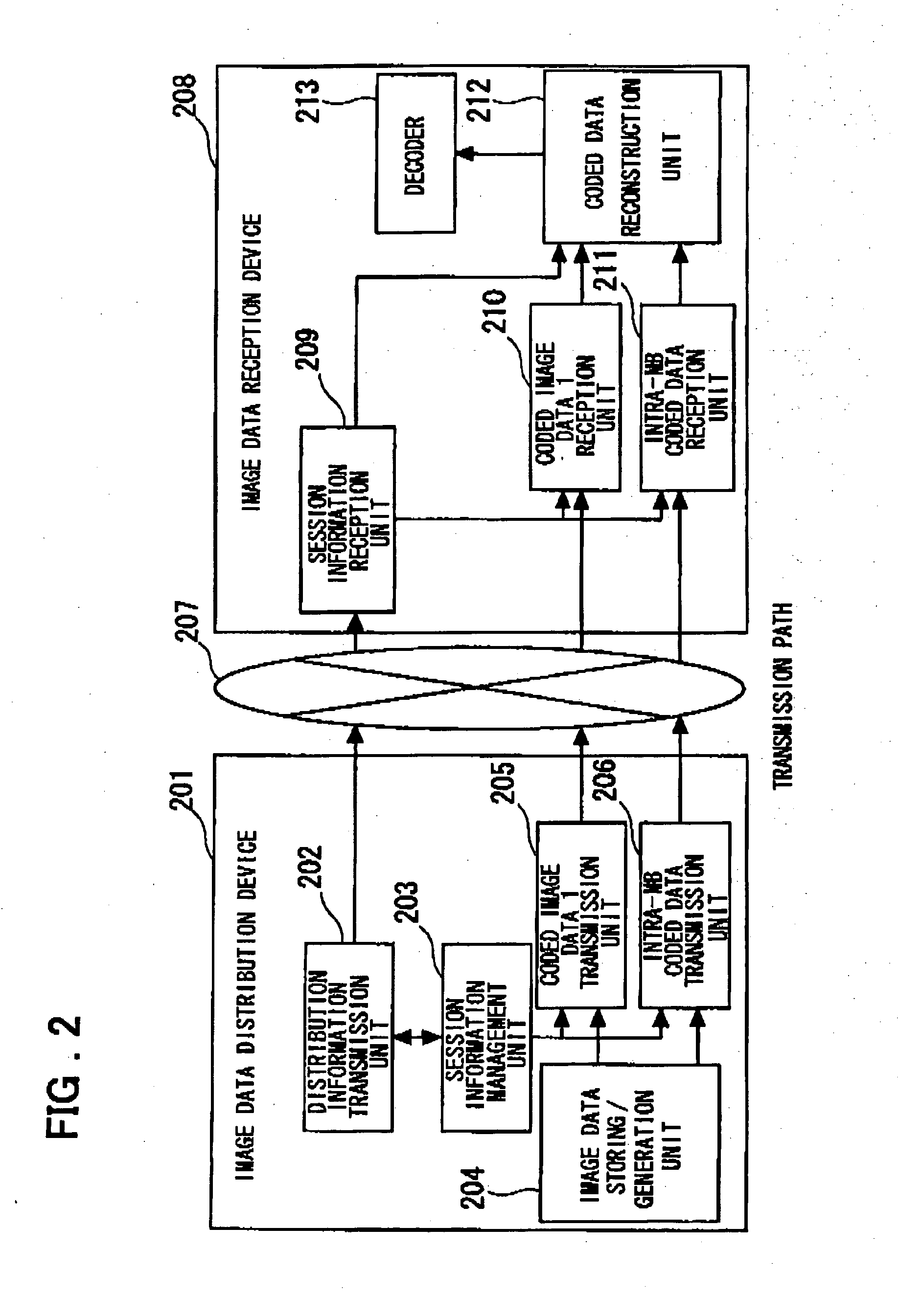
[0110] In a second embodiment of the invention, the image data distribution device comprises: means for distributing both moving image data and coded data for at least part of a frame of moving image data that has been coded in intra-macro-blocks in different sessions, and means for setting routing priority control in the case of a transmission path, or setting power control in the case of a wireless transmission path for each session for distributing moving image data. Also, the image data reception device comprises: means for receiving data that is distributed in at least one session, and means for selecting data from among the received moving image data based on image quality, and then reconstructing and decoding that data as single moving image data. Furthermore, construction is also possible in which a means is included for selecting whether or not to receive the data of at least one session based on at least one of the error / loss ratio of received data, the usa...


PUM


Abstract

An image data distribution device (101) includes an image coded data 1 transmission unit (105), an image coded data 2 transmission unit (106), and a session management unit (103). A plurality of image coded data of the same image is distributed in different sessions or image data having different types of image frame and image block is distributed in different sessions. Here, for each session, the routing priority control is performed in the transmission path and power control is performed if the path is a radio transmission path. An image data reception device (108) includes an image coded data 1 reception unit (110), an image coded data 2 reception unit (111), a session information reception unit (109), a coded data reconstruction unit (112) for reconstructing the coded data, and a decoder (113). Among the image coded data normally received from at least one session, coded data is selected according to the image quality and decoded.

Description

TECHNICAL FIELD [0001] This invention relates to a method, device and system for distributing coded image data, and a computer program that is executed by a computer comprising a distribution device and reception device for image data, and more particularly to a method, device, system and computer program that are suitable for making it possible to reproduce an image with good quality according to the reception environment of moving image data and like by the reception device. BACKGROUND ART [0002] In recent years, many methods of transmitting data that has been coded using high efficiency compression based on inter frame prediction have been used as methods for efficiently transmitting moving image data. In these methods, by predicting a coded image from the previous and following frame in time and then coding the prediction parameters and prediction residual image data that are obtained, the amount of information for moving image data having high correlation in the time direction ...

Claims


Application Information

Patent Timeline
Patent Type & Authority Applications(United States)
IPC IPC(8): G06F3/12H04N7/16H04N7/173H04N7/24H04N21/226H04N21/2383H04N21/426H04N21/438H04N21/61H04N21/6437
CPCH04L1/0009H04L1/0014H04L1/0033H04L1/02H04N7/162H04N21/6405H04N21/23476H04N21/4516H04N21/454H04N21/4621H04N21/23439H04N21/647
Inventor DEI, HIROAKI
Owner RAKUTEN INC
Learn More