
Backlight unit for flat panel display and flat panel display apparatus having the same

a flat panel display and backlight unit technology, applied in lighting and heating apparatus, lighting device details, instruments, etc., can solve problems such as degraded image quality and display performance, and achieve the effect of uniform brightness distribution and simple structur

Active Publication Date: 2006-12-21
SAMSUNG ELECTRONICS CO LTD
View PDF4 Cites 22 Cited by
  • Summary
  • Abstract
  • Description
  • Claims
  • Application Information

AI Technical Summary

Benefits of technology

The present invention provides a backlight unit for a flat panel display that can acquire surface light that exits perpendicularly to the surface of the backlight unit with uniform brightness distribution across the entire light-emitting surface. The invention includes a holographic pattern that includes a plurality of diffraction gratings that continuously repeat on at least one of the exit surface of the light guide panel and the opposing surface and diffracts light incident into the light guide panel. The depth of the diffraction gratings progressively increases away from the incident surface along a length direction of the light guide panel. The backlight unit may further include a transmissive diffusion plate and a reflective member. The invention provides a flat panel display apparatus with a simple structure and improved brightness distribution.

Problems solved by technology

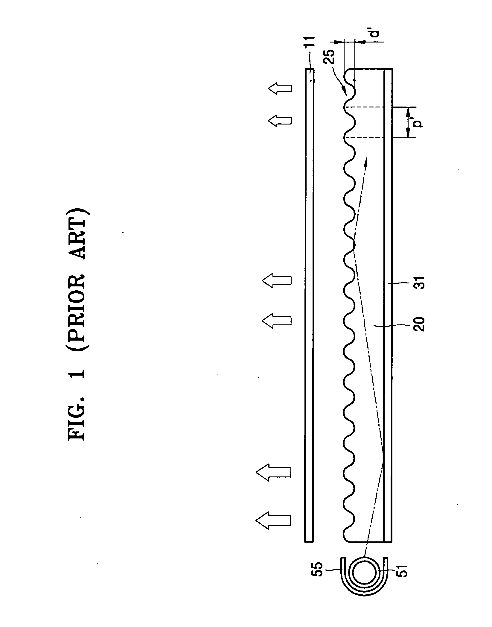
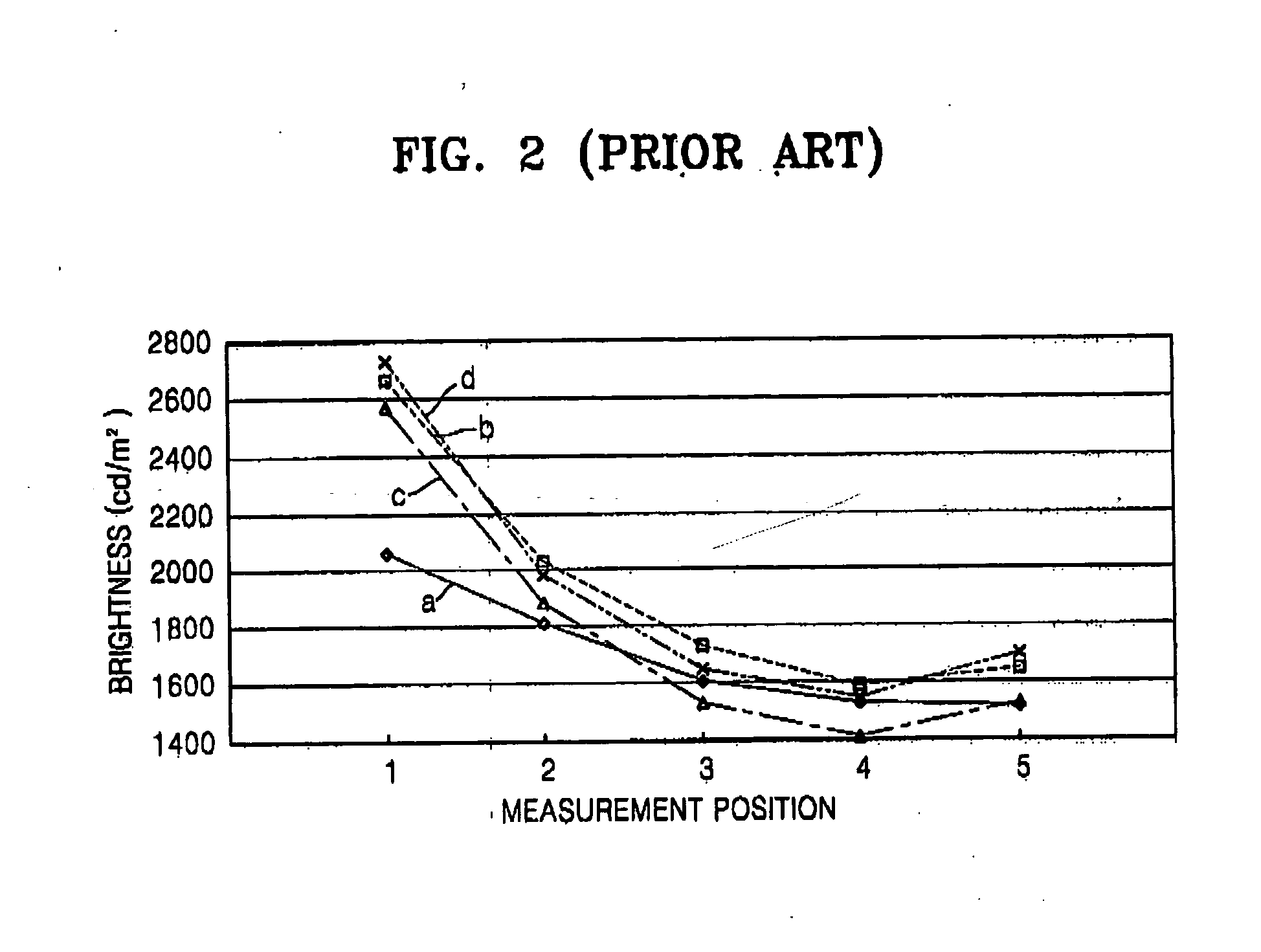
Because emission brightness obtained from the backlight unit has a large variation depending on measurement position, a flat panel display apparatus employing the backlight unit suffers a variation in brightness level depending on position on a display surface and a blemish in brightness, thus providing degraded image quality and display performance.

Method used


Image

  • Backlight unit for flat panel display and flat panel display apparatus having the same
  • Backlight unit for flat panel display and flat panel display apparatus having the same
  • Backlight unit for flat panel display and flat panel display apparatus having the same

Examples


Embodiment Construction

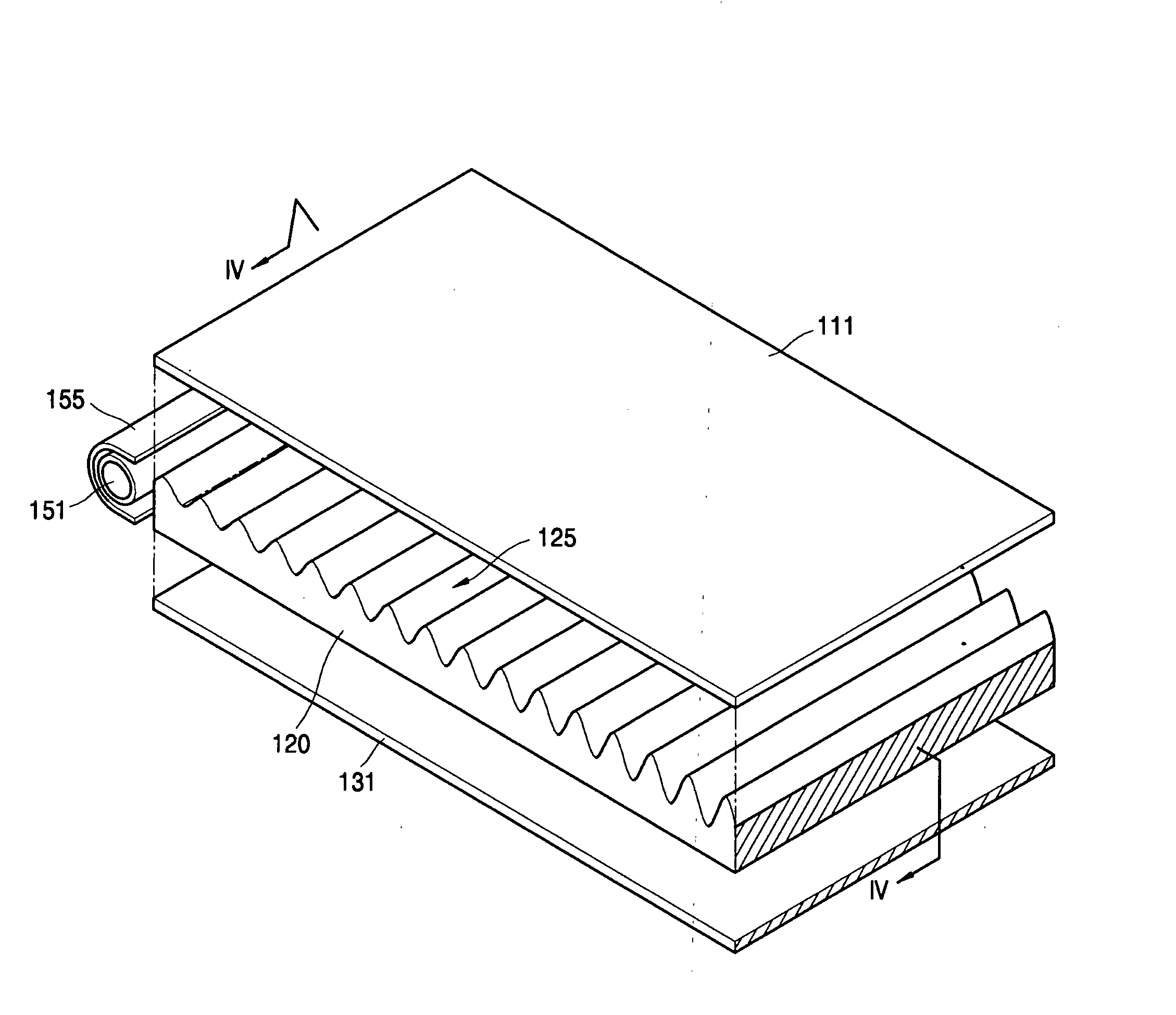
[0027] A backlight unit for a flat panel display and a flat panel display apparatus having the same according to illustrative, non-limiting embodiments of the present invention will now be described in detail with reference to the accompanying drawings. FIGS. 3 and 4 show an edge light type backlight unit as a backlight unit for a flat panel display according to a first embodiment of the present invention. Referring to FIG. 3, the backlight unit for a flat panel display includes a light source 151 producing and emitting light and a light guide panel (LGP) 120 totally internally reflecting light emitted by the light source 151 on one side so that the light can propagate to the other side. The LGP 120 has a holographic pattern 125 diffracting light upward at a top surface thereof.

[0028] The light source 151 may be a white light source supplying white light of multiple wavelengths. In the present embodiment, the light source 151 may be a linear light source having a line-shaped light-...


PUM


Abstract

A backlight unit for a flat panel display and a flat panel display apparatus having the same. The backlight unit for a flat panel display displaying a predetermined image includes: a light source which emits light; a light guide panel having an incident surface facing the light source and which totally reflects light incident through the incident surface toward the flat panel display; and a holographic pattern that includes a plurality of diffraction gratings that are continuously repeated on at least one of an exit surface of the light guide panel and the opposing surface and diffracts light incident into the light guide panel. A depth of the diffraction grating progressively increases away from the incident surface along a length direction of the light guide panel. The backlight unit for a flat panel display and the flat panel display apparatus having the same have a simple structure that can acquire surface light using a holographic pattern while achieving uniform brightness distribution across the entire light-emitting surface.

Description

CROSS-REFERENCE TO RELATED PATENT APPLICATION [0001] This application claims priority from Korean Patent Application No. 10-2005-0052726, filed on Jun. 18, 2005, in the Korean Intellectual Property Office, the disclosure of which is incorporated herein in its entirety by reference. BACKGROUND OF THE INVENTION [0002] 1. Field of the Invention [0003] The present invention relates to a backlight unit for a flat panel display and a flat panel display apparatus having the same and, more particularly, to a backlight unit for a flat panel display with a uniform brightness gradient across the entire light-emitting surface and a flat panel display apparatus having the same. [0004] 2. Description of the Related Art [0005] Unlike self-emissive flat panel displays, non-emissive flat panel displays, such as liquid crystal display (LCD) panels, need external light to produce an image. Thus, a backlight unit is located behind a non-emissive flat panel display and illuminates light on the flat pane...

Claims


Application Information

Patent Timeline
Patent Type & Authority Applications(United States)
IPC IPC(8): G02B5/32
CPCG02B6/0038G02F2001/133507G02B6/0061G02B6/0051G02F1/133507G02F1/1335
Inventor CHOI, YOON-SUNCHOI, JIN-SEUNGMIN, JEE-HONGKIM, JIN-HWANLEE, SU-MI
Owner SAMSUNG ELECTRONICS CO LTD
Learn More