

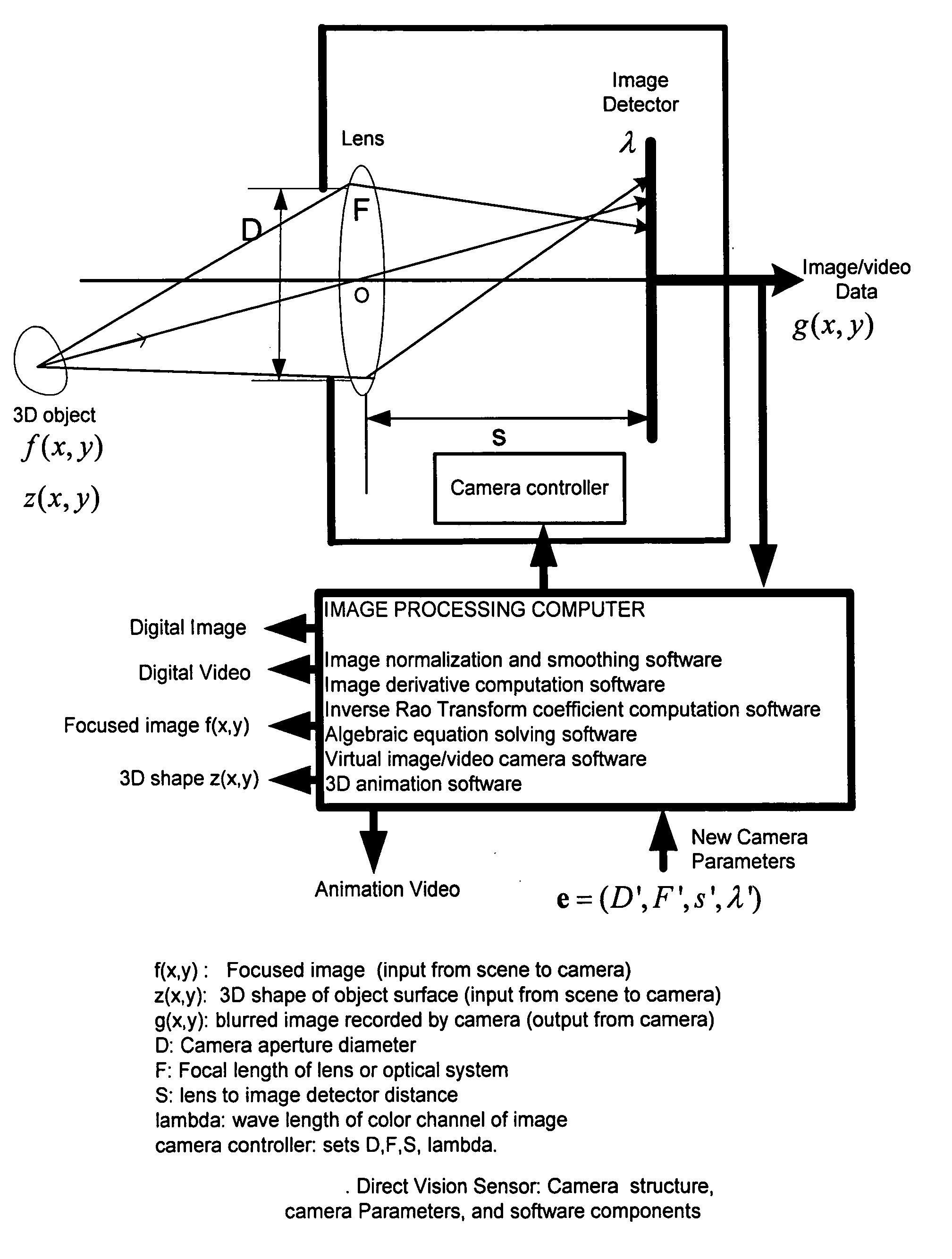
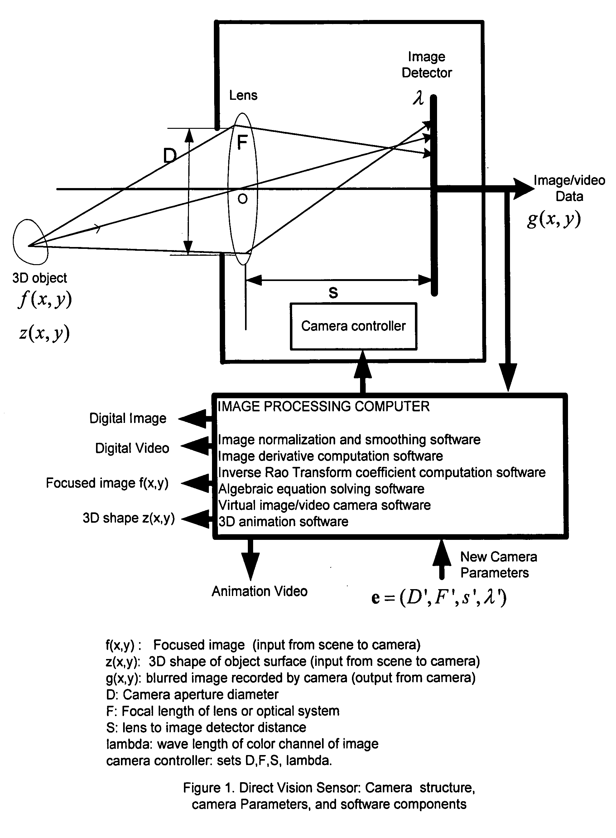
Direct vision sensor for 3D computer vision, digital imaging, and digital video
a technology of computer vision and direct vision, applied in image enhancement, image analysis, details involving processing steps, etc., can solve problems such as inaccurate or inaccurate results in practice, method and apparatus are useful, and assumption is often incorrect in a physical camera
- Summary
- Abstract
- Description
- Claims
- Application Information
AI Technical Summary
Benefits of technology
Problems solved by technology
Method used
Image

Examples
example 1
Gaussian SV-PSF
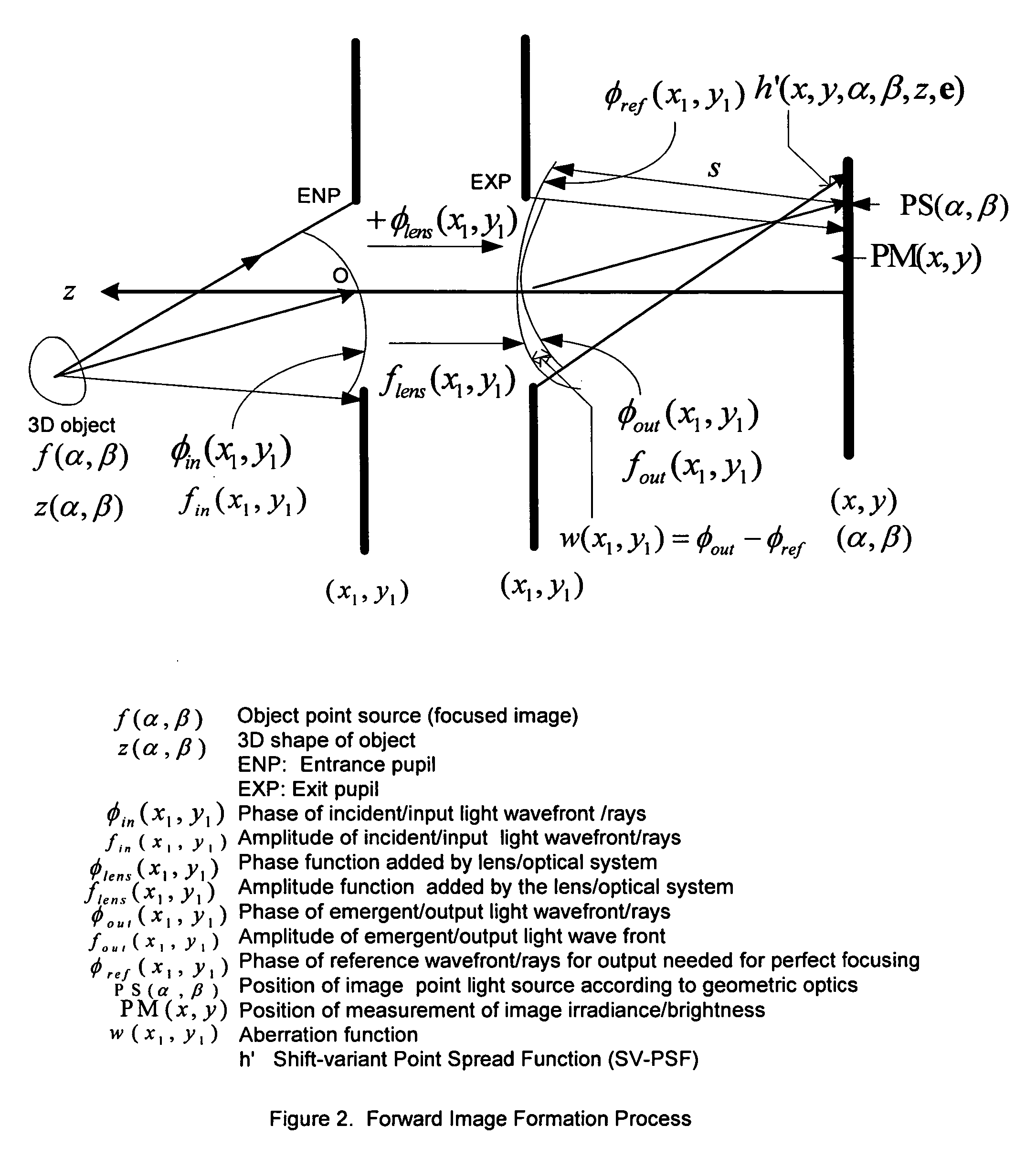
[0060] There are many models for the point spread function of a camera. The method of the present invention is applicable to all models. To illustrate the method of the present invention, first a popular model of the point spread function which is a Gaussian function is considered. Later, another model derived from paraxial geometric optics is considered. When the SV-PSF is a 2D Gaussian, the non-localized SV-PSF h′ is given by h′(x,y,α,β,ep,z(α,β))=12πσp2(α,β,z(α,β))exp(-(x-α)2+(y-β)22σp2(α,β,z(α,β)))(23)
[0061] Note that, with this definition, Equation (4) that gives the relation between the shift-variant blurred image and the focused image will be valid, i.e.
gp(x,y)=∫−∞∞∫−∞∞h′(x,y,α,β,ep,z)f(α,β)dαdβ. (24)
Also, the parameter σp is approximately proportional to the blur circle radius Rp given by the relation σp=Rp / √{right arrow over (2)}.
[0062] Now, we use the novel Rao Localization Transform to get the localized PSF h as below:
h(x,y,α,β,ep,z(x,y))...
example 2
Cylindrical or Pill-Box SV-PSF: Paraxial Geometric Optics
[0066] In the preferred embodiment of the present invention, the shape of the camera aperture is circular. Therefore the point spread function has a non-zero constant value inside a circular region and has a zero value outside of the circular region. This circular region is also referred to as “blur circle”. The point spread function in this case is circularly symmetric about the center of the blur circle.
[0067] In the paraxial geometric optics model of image formation, the non-localized SV-PSF h′ is given by a cylindrical function defined by h′(x,y,α,β,ep,z(α,β))={1π Rp2(α,β,z(α,β))for (x-α)2+(y-β)2≤Rp2(α,β,z(α,β))0otherwise.(39)
Note that, with this definition, Equation (4) that gives the relation between the shift-variant blurred image and the focused image will be valid, i.e.
gp(x,y)=∫−∞∞∫−∞∞h′(x,y,α,β,ep,z)f(α,β)dαdβ. (40)
Now, we use the Rao Localization Transform to get the localized PSF h as below:
h(x,...
PUM
 Abstract
Description
Claims
Application Information