
Flow channel on interconnect of planar solid oxide fuel cell

a fuel cell and flow channel technology, applied in the direction of fuel cell details, fuel cells, electrochemical generators, etc., can solve the problems of increased complexity in production, increased cost, and other problems, and achieve the effect of reducing the temperature difference in the fuel cell, improving reliability of operation, and even and smoothly flowing operation

Inactive Publication Date: 2006-12-21
INST NUCLEAR ENERGY RES ROCAEC +1
View PDF3 Cites 17 Cited by
  • Summary
  • Abstract
  • Description
  • Claims
  • Application Information

AI Technical Summary

Benefits of technology

[0022] Therefore, the main purpose of the present invention is to evenly and smoothly flow operation flows of a fuel cell to an interconnect to uniform the current density distribution of an electricity generation substrate by way of a first and a second flow areas. As a result, the temperature differential in the fuel cell is lowered; the reliability of operation is improved; the performance of the fuel is elevated; and the usage period of the fuel cell is prolonged.
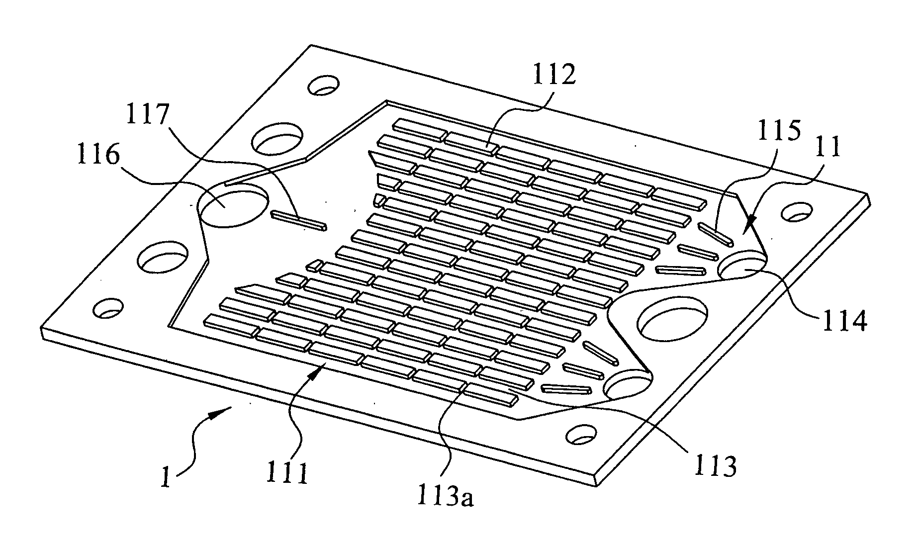
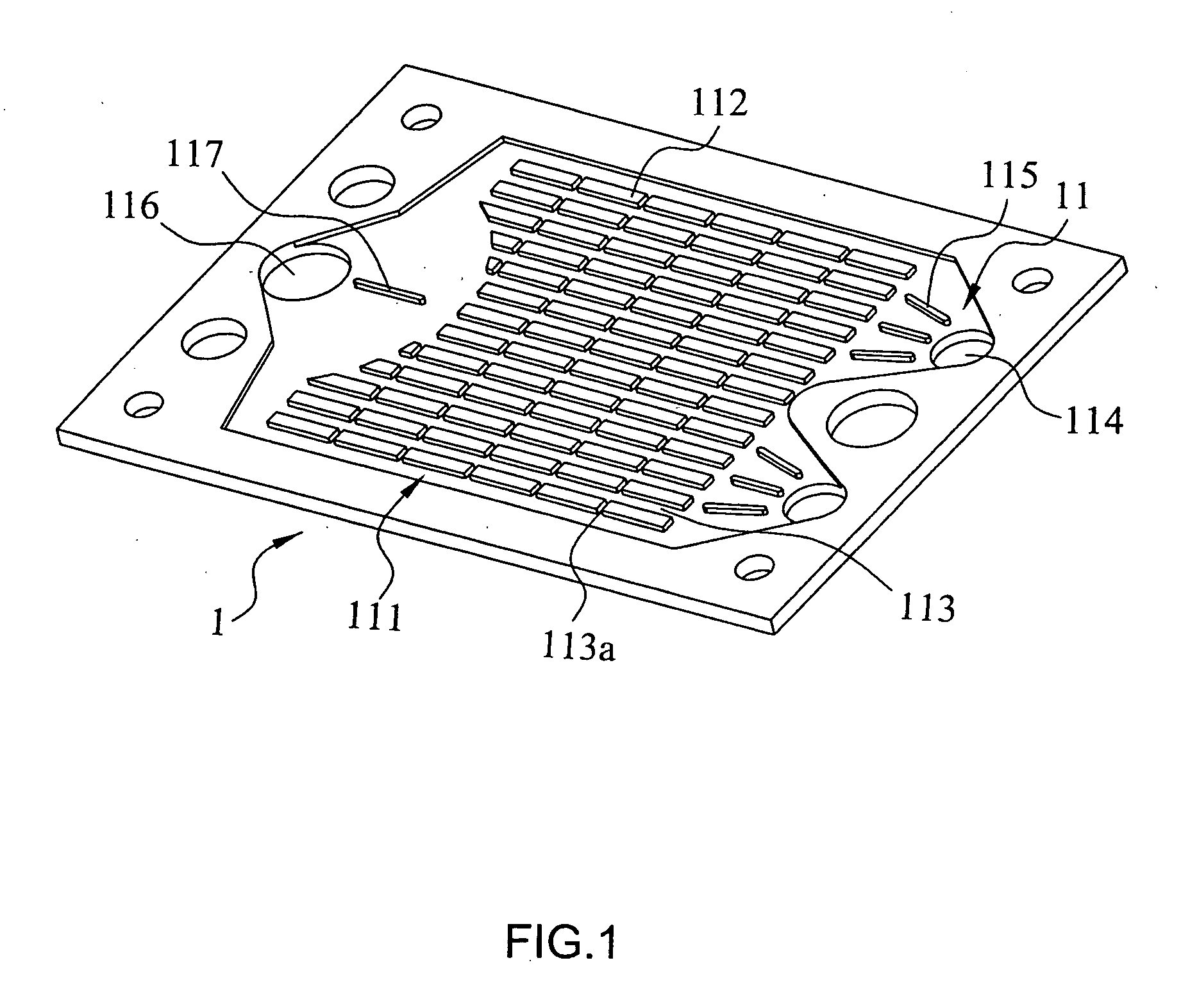
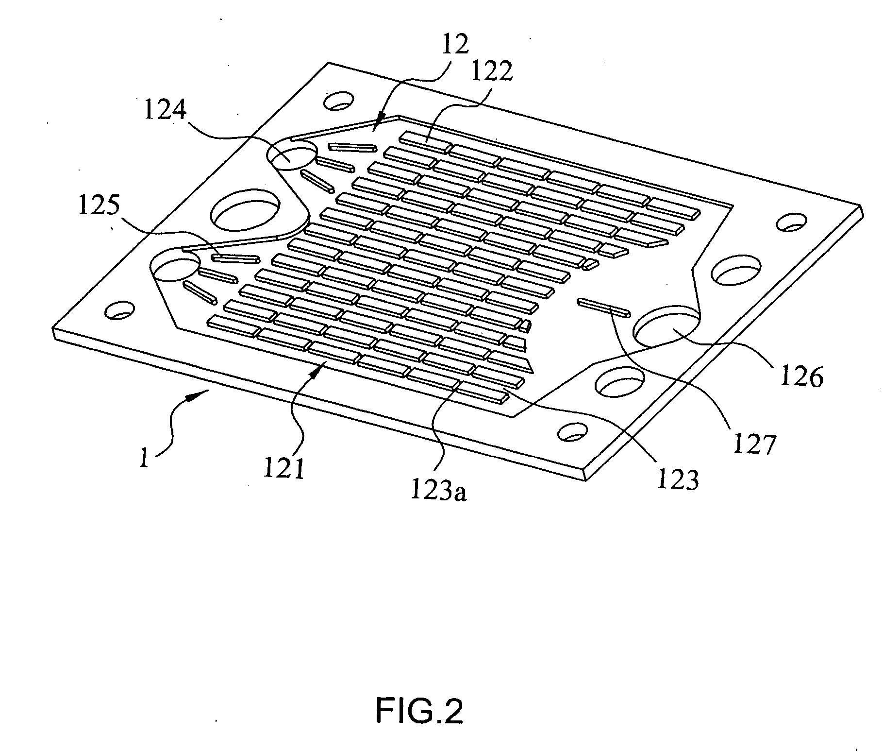
[0023] To achieve the above purpose, the present invention is a flow channel on an interconnect of a planar SOFC, comprising a first flow area and a second flow area. The first flow area is deposed on a surface of the interconnect, comprising a first channel, at least one inlet at an end connecting with the first channel, and an outlet at the other end connecting with the first channel. The second flow area is deposed on the opposite surface of the interconnect, comprising a second channel, at least one inlet at an end connecting with the second channel while deposed at two sides of the outlet of the first flow area, and an outlet at the other end connecting with the second channel while deposed between the inlets of the first flow area. Accordingly, operation flows of the fuel cell can evenly and smoothly flow to the interconnect to uniform the current density distribution of the electricity generation substrate by way of the first and the second flow areas. As a result, the temperature differential in the fuel cell is lowered; the reliability of operation is improved; the performance of the fuel is elevated; and the usage period of the fuel cell is prolonged.

Problems solved by technology

But, in the process of commercializing the FC, some technique obstacles have come up with.
On the contrary, the more the number of the inlets and outlets is, the faster the velocity of the fluid is, although with more complex design as a whole, with increased complexity in production, and with much more cost.

Method used


Image

  • Flow channel on interconnect of planar solid oxide fuel cell
  • Flow channel on interconnect of planar solid oxide fuel cell
  • Flow channel on interconnect of planar solid oxide fuel cell

Examples


Embodiment Construction

[0034] The following descriptions of the preferred embodiments are provided to understand the features and the structures of the present invention.

[0035] From a viewpoint of flood prevention, a buffer area like a reservoir helps to slow down the velocity of a stream; besides, a design of divisional islands make a stream detoured to uniform the velocity of the stream by lengthening the distance. And, as what a turbine-blade equilibrated valve can do, the idea of such a valve can be extendedly applied to an equilibrium slot between the ribs of the interconnect so that the velocity can be uniformed by balancing the pressure with the design of the slot. Besides, a deflector also helps uniform the velocity. Thus, the above-stated are the main ideas and principles according to the present invention.

[0036] Please refer to FIG. 1 and FIG. 2, which are a perspective view and another perspective view of a first preferred embodiment according to the present invention. As shown in the figures...


PUM


Abstract

The present invention is a flow channel on an interconnect of a planar solid oxide fuel cell, comprising a first flow area and a second flow area where operation flows of a fuel cell flow evenly and smoothly to the interconnect to uniform the current density distribution of an electricity generation substrate, while the temperature differential in the fuel cell is lowered; the reliability of operation is improved; the performance of the fuel is elevated; and the usage period of the fuel cell is prolonged.

Description

FIELD OF THE INVENTION [0001] The present invention relates to an interconnect of a fuel cell; more particularly relates to evenly and smoothly flowing operation flows of the fuel cell to the interconnect to uniform current density distribution of an electricity generation substrate while the temperature differential in the fuel cell is lowered; the reliability of operation is improved; the performance of the fuel is elevated; and the usage period of the fuel cell is prolonged. DESCRIPTION OF THE RELATED ART(S) [0002] Energy is the foundation for exploiting the resources on the earth. In another word, the development of the technologies and the exquisite lives we have nowadays are all based on efficiently utilizing the energy. Nevertheless, electricity is of no doubt the most convenient energy for human; therefore, for centuries, the scientists and the engineers have researched in all kinds of energies with much effort to meet the requirements of the economy and the society. Fuel ce...

Claims


Application Information

Patent Timeline
IPC IPC(8): H01M8/02
CPCH01M8/0258H01M8/04007Y02E60/525H01M2008/1293Y02E60/50H01M8/04089H01M8/2483H01M8/2432H01M8/2484
Inventor CHYOU, YAU-PINSHY, SHENGYANGCHENG, YUNG-NENGYEN, CHENG-HO
Owner INST NUCLEAR ENERGY RES ROCAEC
Learn More