Axial flow fan improvements

a technology of axial flow fans and fans, which is applied in the direction of lighting and heating apparatus, ventilation systems, heating types, etc., can solve the problems of imposing severe demands on fans, affecting production, and indoor conditions becoming much hotter than before, and achieves the effect of quiet operation and effectively overcoming prior art drawbacks

Inactive Publication Date: 2006-12-21
MILANA ANGELO
View PDF3 Cites 33 Cited by
  • Summary
  • Abstract
  • Description
  • Claims
  • Application Information

AI Technical Summary

Benefits of technology

[0026] The present invention relates to an axial flow fan that is particularly quiet in operation and effectively overcomes the prior art drawbacks.

Problems solved by technology

Intensive rearing of birds (typically more than 10 000) imposes severe demands on the fans which are provided for removing moisture, heat, carbon dioxide and other contaminants from said buildings.
Hot summer days often cause indoor conditions to become much hotter than desired, temperatures above 25 degree Celsius have an adverse effect on production of said birds.
As a result, when wind blows against the fans, the air flow decreases substantially and will not be sufficient to cool the birds which will suffer of heat stress.
However, the solution is not satisfactory because increases the capital cost and the operating cost due to an increase of energy consumption.
As it can be imagined, the large number of vanes constitutes an obstruction to air flow and raise the cost of the fan, which is also increased by the cost of labor required to assemble the large quantity of vanes and elements connecting them.
Any reduction in needed air flow can reduce bird performance and increases mortalities of the birds.
As a result, the fans are bulkier and heavier and the manufacturing and shipping costs are significantly higher.
The poultry house fans may operate continuously generating also undesirable noise and vibrations.
Vibrations and excessive noise of the fans mainly are caused by the air pushed by the propeller and passing across the vanes which oscillate.
Another important source of noise is caused by the blades of the propeller which during its rotational movement over obstacles produce a pressure variation on the obstacle which results in noise emission.
Since the function of the propeller blades is to move air in a direction parallel to a rotational axis, velocities imparted in other directions represent degradation in efficiency, increase of the noise and cost to operate the fan.
In particular, the air flow around the tip region of said propeller blades creates a very noisy and strong vortex trailing downstream from the blade tips.
Heretofore, it was necessary to ship a large amount of “air” in the assembled fans at a cost that became significant especially with overseas shipments.
Another problem encountered with axial flow fans used in poultry house buildings includes the drive belt.
Over time, a typical V-belt will eventually wear and the tension transmitted by the belt will vary causing slippage and reduction of fan air flow.
The above patents have been fully described in my referred patent and patent application and show propeller fans comprising a centrifugal mechanism designed to operate positively the shutter vanes which are made of thin metal providing relatively poor insulating qualities, said vanes lack positive seals which do not permit them to be used effectively in severe and cold climate areas.

Method used


Image

  • Axial flow fan improvements
  • Axial flow fan improvements
  • Axial flow fan improvements

Examples


second embodiment

[0086] With reference to FIGS. 9A, 9B, 9C, 10, and FIG. 11, the present invention is shown and described.

[0087] The axial flow fan 10″ of the present invention is similar to the fan 10 herein above described and comprises similar components as the fan 10 of the first embodiment of the invention set above. However, the housing 11″ is more compact than housing 11, a centrifugal mechanism 33″ (similar to the 33) is rotatably connected to the shutter assembly 39″ which comprises a pair of vertically pivoting doors 41″ and 42″ opened and closed by said centrifugal mechanism 33″ that is mounted to one end of a fan hollow shaft 21″ opposite to the propeller 20A and comprises an axial sliding reciprocating actuator member 56″ mounted on a hollow guide 54″. The reciprocating actuator member 56″ comprises a compression operative biasing means 64″ and an operative rod 201 adapted to pass through the fan hollow shaft 21″. The operative rod 201 is threaded and fastened with nut 202 to one end to...

fourth embodiment

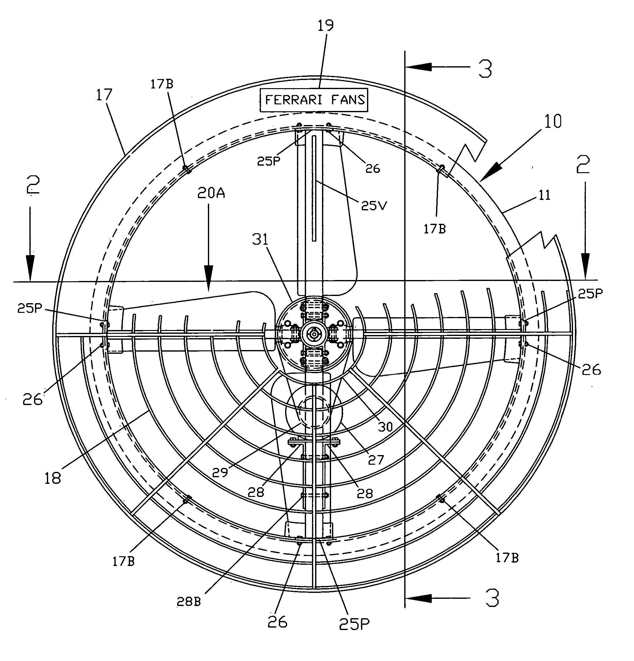
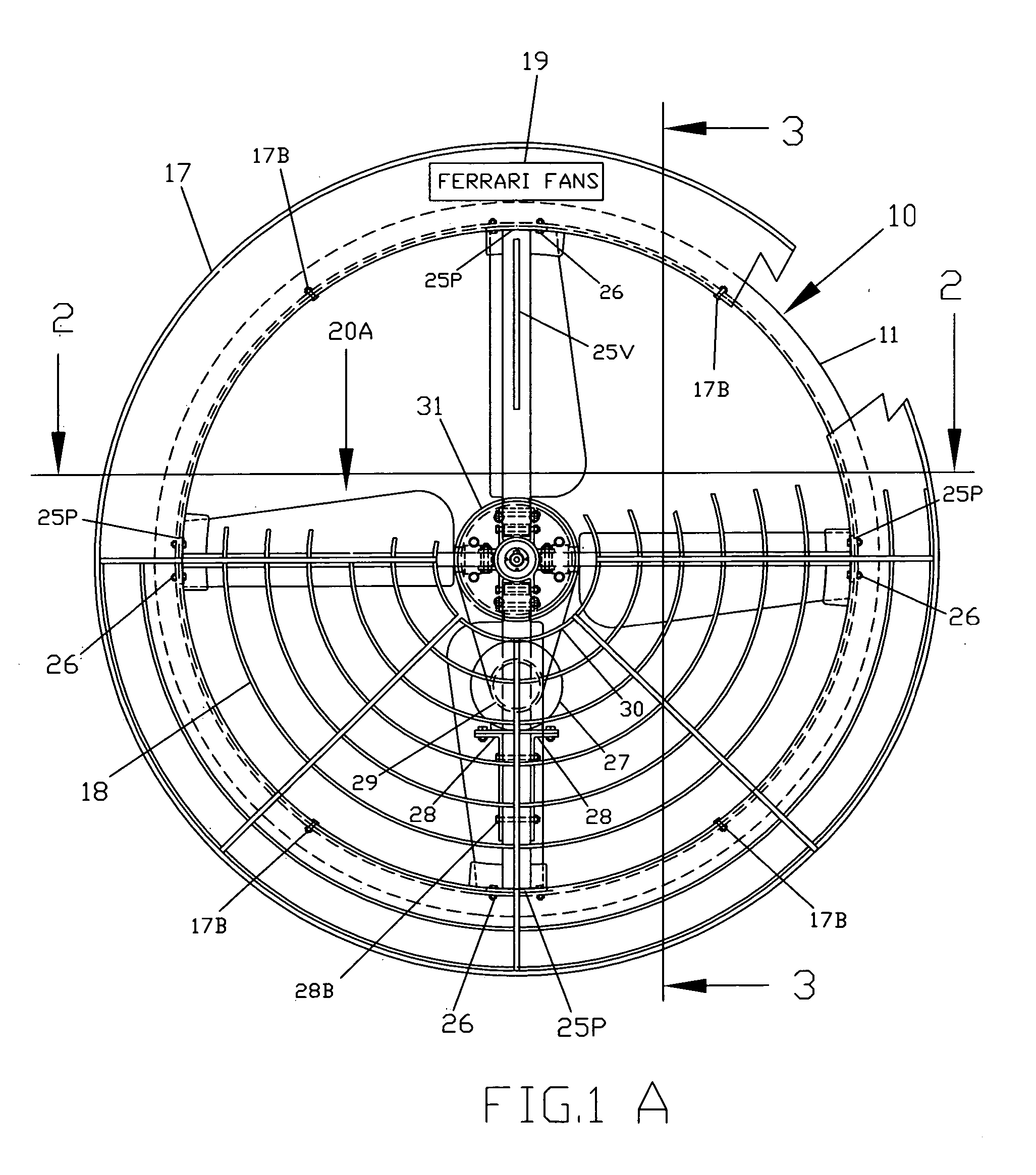
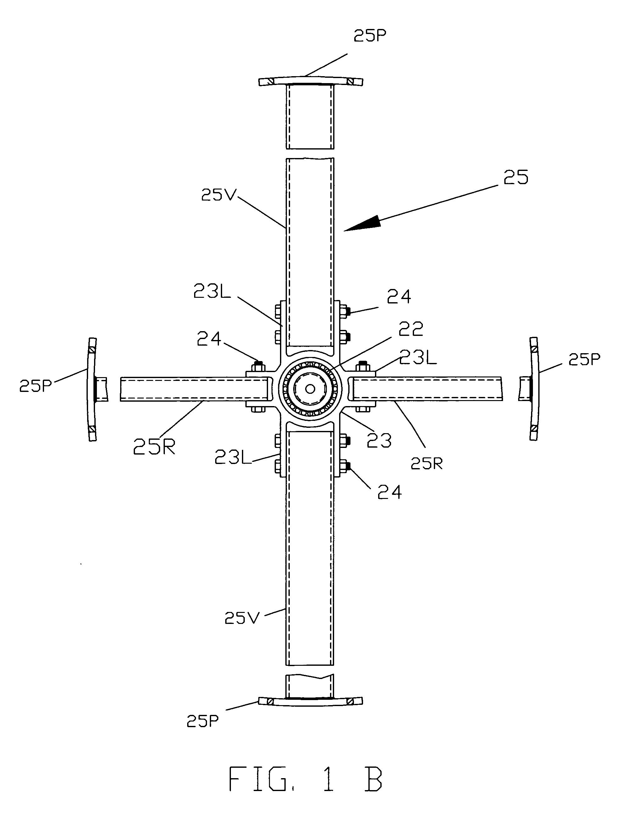
[0094] With reference now to FIGS. 17A, 17B, FIG. 18 and FIG. 19 the present invention is illustrated and described. The axial flow fan 400 of the present invention comprises a cylindrical shaped housing 411 comprising an air intake end 412 and an air output end 413. The fan housing 411 is preferably made of one-piece of rolled steel or aluminium sheet metal. The air intake end 412 is provided with a bell shaped mouth 17 secured with mechanical fasteners 17B thereto and is provided with a bracket 25″ (similar to the bracket 25 of FIG. 1B) secured with mechanical fasteners 25B″ to four opposite sides of said air intake end for supporting a propeller 20A best shown in FIGS. 4, 5 and 6).

[0095] A shutter assembly 439 is mounted at the fan discharge end 413 and comprises a plurality of even angularly spaced pair of vanes 414 comprising leading edges connected to each other with a hinge 414H comprising four intersecting rods including a horizontal stationary rod 209″R and a stationary ver...


PUM


Abstract

An energy efficient and compact axial fan with a housing comprising a fan assembly comprising a drive motor and a propeller coupled thereto. The inlet opening and/or the outlet opening of the fan housing are provided with a shutter assembly positioned adjacent the propeller and having a plurality aerodynamically shaped pivoted louvers working in tandem for less air obstruction and noise. The propeller comprises a plurality of radial blades comprising means for straitening the air flow and reducing the vortex flow of the propeller thereby permitting the shutter to be mounted adjacent the propeller to lessen the dept of the fan housing for making the fan more compact.

Description

BACKGROUND OF THE INVENTION [0001] 1. Field of the Invention [0002] The invention disclosed herein relates generally to axial flow fans improvements and, more particularly to axial flow fans having a shutter operated by a centrifugal mechanism for maintaining a controlled environment in buildings such as poultry houses, greenhouses, steel-plants, foundries, etc. [0003] 2. Description of the Related Art [0004] Axial flow fans are used to move high volume of air at low static pressure. An application in which they are beneficially used involves the ventilation of poultry house buildings which often are shaped like a tunnel. Intensive rearing of birds (typically more than 10 000) imposes severe demands on the fans which are provided for removing moisture, heat, carbon dioxide and other contaminants from said buildings. [0005] Hot summer days often cause indoor conditions to become much hotter than desired, temperatures above 25 degree Celsius have an adverse effect on production of sai...

Claims


Application Information

Patent Timeline
Patent Type & Authority Applications(United States)
IPC IPC(8): F24F7/00
CPCF04D25/0613F24F7/007F04D25/14F04D25/06
Inventor MILANA, ANGELO
Owner MILANA ANGELO
Why Eureka
Try Eureka