Adjustable fixation clamp and method

a fixation clamp and adjustable technology, applied in the field of fixation clamps, can solve problems such as the bulging of the fixation system

Active Publication Date: 2006-12-21
DEPUY SYNTHES PROD INC
View PDF48 Cites 129 Cited by
  • Summary
  • Abstract
  • Description
  • Claims
  • Application Information

AI Technical Summary

Benefits of technology

[0008] The vise plates may be configured so as to prevent rotation about the longitudinal axis between the first and second vise plates as well as between the third and fourth vise plates. In one embodiment, the first vise plate may have at least one post which may be positioned within at least one opening of the second vise plate. In another embodiment, the second vise plate may have at least one post which may be positioned within at least one opening of the first vise plate. In another embodi

Problems solved by technology

With current clamps, this requires the use of at least four separate clamps in an external

Method used


Image

  • Adjustable fixation clamp and method
  • Adjustable fixation clamp and method
  • Adjustable fixation clamp and method

Examples


Embodiment Construction

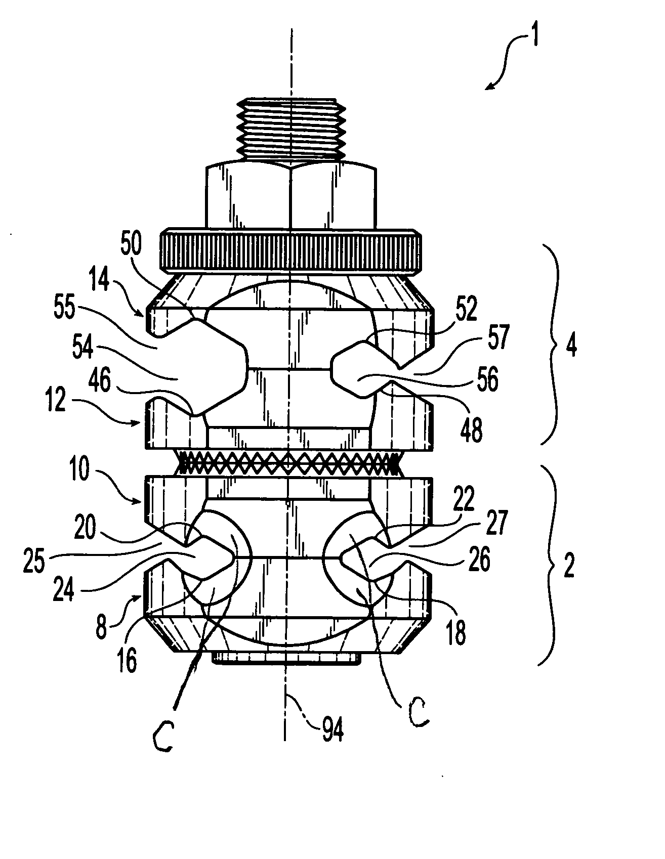
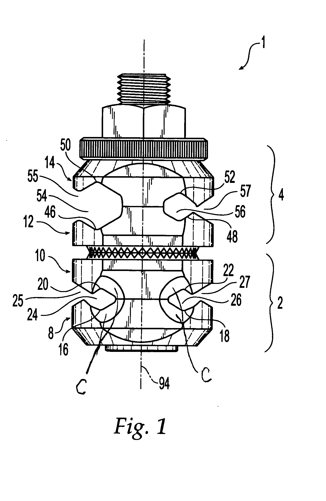
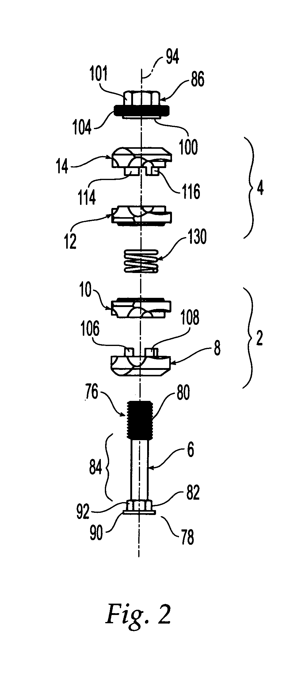
[0027] As shown in FIGS. 1 and 2, the adjustable clamp 1 may include a first clamp assembly 2 and a second clamp assembly 4. The clamp assemblies 2, 4 may be connected to each other by a shaft 6, which may be positioned through a longitudinal bore in the clamp assemblies 2, 4. The shaft 6 may be positioned along the longitudinal axis 94 of the adjustable clamp 1. It should, however, be understood that those of ordinary skill in the art will recognize many modifications and substitutions which may be made to various elements of the present invention.

[0028] The first clamp assembly 2 may have a lower or first vise plate 8 and an upper or second vise plate 10. Similarly, the second clamping portion 4 may include a lower or third vise plate 12 and an upper or fourth vise plate 14. Vise plates 8, 10, 12 and 14 may be made of any suitable material, preferably biocompatable material, such as metal (e.g., stainless steel, titanium, aluminum), plastic, rubber, an alloy of two or more materi...


PUM


Abstract

An adjustable fixation clamp having first and second clamp assemblies positioned about a shaft. The clamp assemblies may each have a pair of vise plates. Each pair of vise plates may define at least two receiving portions and insertion portions intersecting the receiving portions. The receiving portions of one clamp assembly may receive at least two fixation components such as screws, pins or wires. The receiving portions of the other clamp assembly may receive at least one connector such as a rod, bar and/or ring. A biasing structure may be positioned between the first and second clamp assemblies and may allow for the fixation components to be snapped into the receiving portions through the insertion portions. Two or more adjustable fixation clamps may be used to form an external fixation system. At least two screws, pins or wires may be inserted into bone and one of the clamp assemblies may be attached thereto. A guide may be used for insertion of screws, pins or wires into bone. The other clamp assembly may be connected to a rod, bar or ring. Thereafter, the clamp assemblies may be oriented relative to each other and locked in place.

Description

FIELD OF THE INVENTION [0001] The present invention relates to a fixation clamp and, more particularly, to an adjustable fixation clamp for use in an external fixation system for holding bone fragments adjacent to each other. BACKGROUND OF THE INVENTION [0002] External fixation systems are used to connect two or more bone fragments to each other. For example, external fixation systems have been used to reduce fractures of the mandible, including fractures of the condyle. These devices incorporate bone screws, pins, wires, rods, bars and / or rings to assist in healing of fractured bones and to assure proper alignment of bone. [0003] To provide for external fixation of a bone fracture, at least four points of fixation are generally preferred. Two bone screws, pins or wires are inserted into each bone fragment on opposite sides of a fracture. The bone screws, pins or wires are connected to a fixation rod, bar or ring using clamps, thereby creating an external fixation system. Such a con...

Claims


Application Information

Patent Timeline
IPC IPC(8): A61B17/00
CPCA61B17/645A61B17/6458F16B2/065Y10T24/3439F16M13/02F16M2200/027Y10T24/3958F16B7/0433A61B17/6466A61B17/04A61B17/56A61B17/58
Inventor LESSIG, RICHARD K.CHILTON, ROBERT J. III
Owner DEPUY SYNTHES PROD INC
Why Eureka
Try Eureka