Fault diagnosis apparatus for sensors used in a system

a technology of fault diagnosis and sensor, which is applied in the direction of electric control, instruments, machines/engines, etc., can solve the problems of inability to identify faulty sensors, inability to detect inability to determine faults in sensors b>1001/b> and b>1002/b>, etc., to achieve the effect of increasing costs

Inactive Publication Date: 2006-12-21
HITACHI LTD
View PDF6 Cites 55 Cited by
  • Summary
  • Abstract
  • Description
  • Claims
  • Application Information

AI Technical Summary

Benefits of technology

[0024] The fault diagnosis apparatus for sensors according to the present invention can determine which of at least three sensors that detect different physical quantities is faulty, without the need to pro...

Problems solved by technology

Consequently, a fault in the sensor 1001 cannot be detected.
However, which of the sensors 1001 and 1002 is faulty cannot be determined because no other method is a...

Method used


Image

  • Fault diagnosis apparatus for sensors used in a system
  • Fault diagnosis apparatus for sensors used in a system
  • Fault diagnosis apparatus for sensors used in a system

Examples


Embodiment Construction

[0046] First, description will be given of the principle and utility of a fault diagnosis apparatus for sensors according to the present invention.

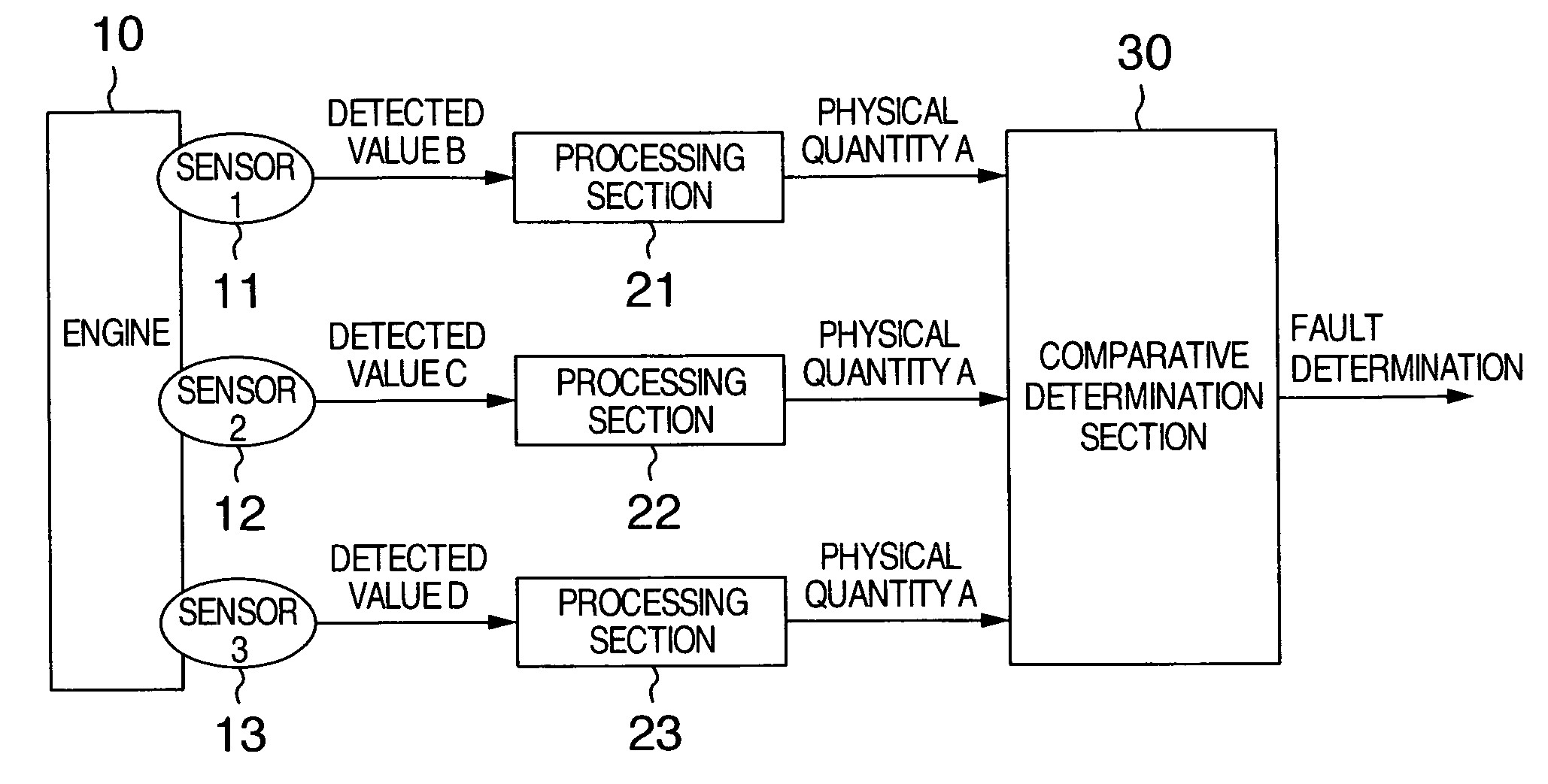
[0047] Control systems for vehicles, power plants, industrial machines, and chemical plants include, for example, sensors that detect the condition of an engine. Many types of sensors that detect various conditions of the engine are provided in these systems to detect different physical conditions. The different physical conditions do not vary completely independently but many of them vary in correlation with one another.

[0048] Accordingly, the same physical quantity can be calculated from detected values (outputs) from sensors detecting different physical conditions of an engine. Thus, for sensors that detect three or more different physical quantities for one physical phenomenon, which of these sensors is faulty can be detected on the basis of a significant difference between one of the sensors and others, by comparing detected values...


PUM


Abstract

A fault diagnosis apparatus for sensors in an apparatus system has at least three sensors which detect different physical quantities for one physical phenomenon which vary in correlation with one another, the sensors outputting signals indicating the detected physical quantities, wherein outputs from the at least three sensors are converted into one identical physical quantity in accordance with the correlations so that the resulting identical physical quantity can be used to determine whether or not each of the sensors is defective.

Description

BACKGROUND OF THE INVENTION [0001] The present invention relates to a fault diagnosis apparatus for sensors in an electric system having three or more sensors, and in particular, to a fault diagnosis apparatus for sensors used in vehicles, power plants, industrial machines, chemical plants and the like. [0002] There has been disclosed condition detection means, that is, a fault diagnosis apparatus for sensors in which a second sensor is provided in addition to a first sensor; the first sensor converts a first physical quantity indicating a behavior (physical phenomenon) of a vehicle into a first measurement signal, and the second sensor converts a second physical quantity indicating a behavior of the vehicle which is different from the first physical quantity into a second measurement signal. Calculation means calculates an approximate value corresponding to the first physical quantity on the basis of the second measurement signal. The calculation means then compares a measurement f...

Claims


Application Information

Patent Timeline
IPC IPC(8): G06F19/00G01C25/00F02D45/00G01D21/00G05B23/02
CPCF02D41/18F02D41/222Y02T10/40G01D3/08F02D2400/08
Inventor HORI, TOSHIO
Owner HITACHI LTD
Why Eureka
Try Eureka