Backlight assembly, display device having the same, and method thereof

a display device and backlight assembly technology, applied in the field of backlights, can solve the problems of difficult to assemble the backlight assembly, complicated rework of the backlight assembly, and difficulty in implementing an entirely planarized light source, and achieve the effect of improving the connection structure of the metal core printed circuit board

Active Publication Date: 2006-12-28
SAMSUNG DISPLAY CO LTD
View PDF4 Cites 115 Cited by
  • Summary
  • Abstract
  • Description
  • Claims
  • Application Information

AI Technical Summary

Benefits of technology

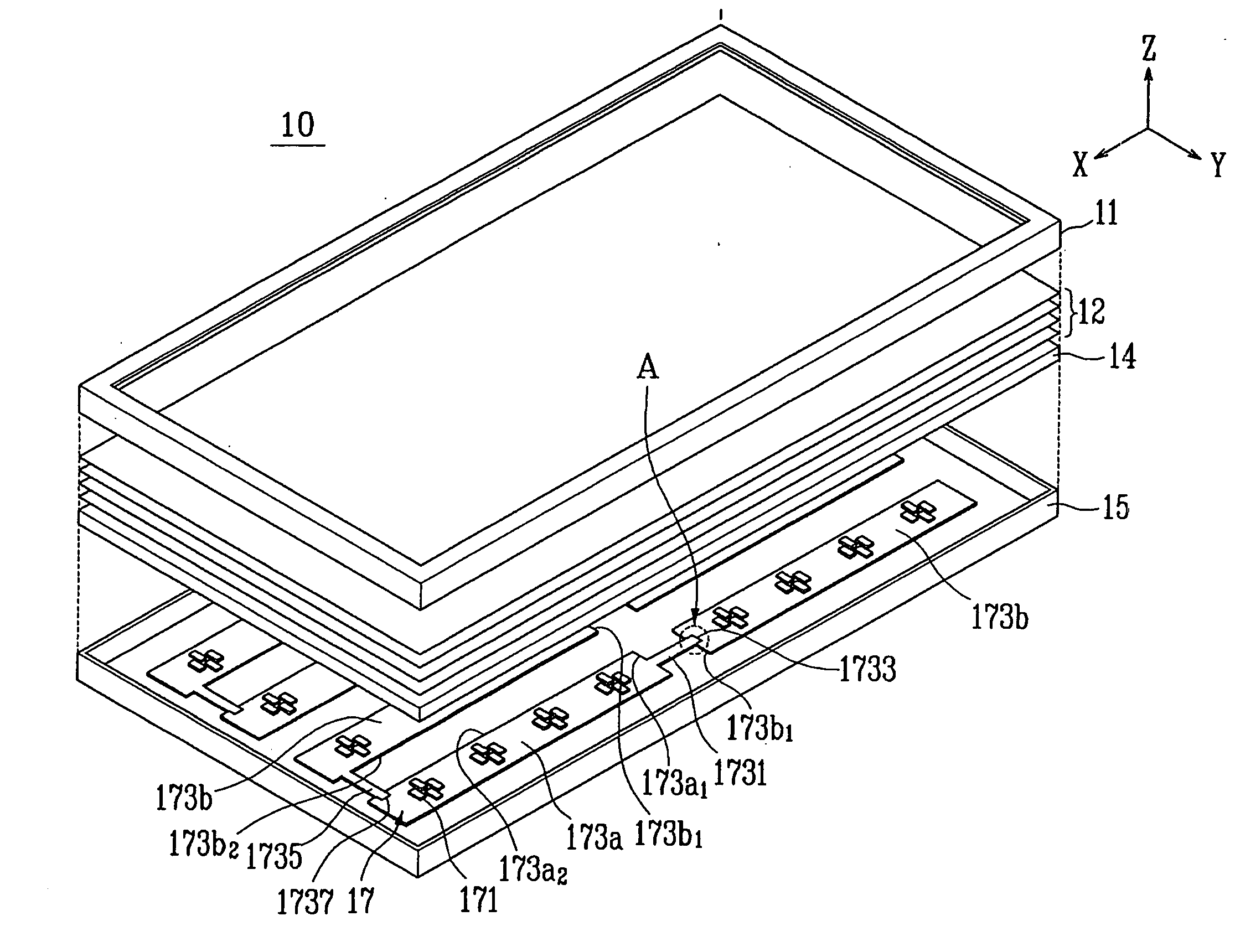
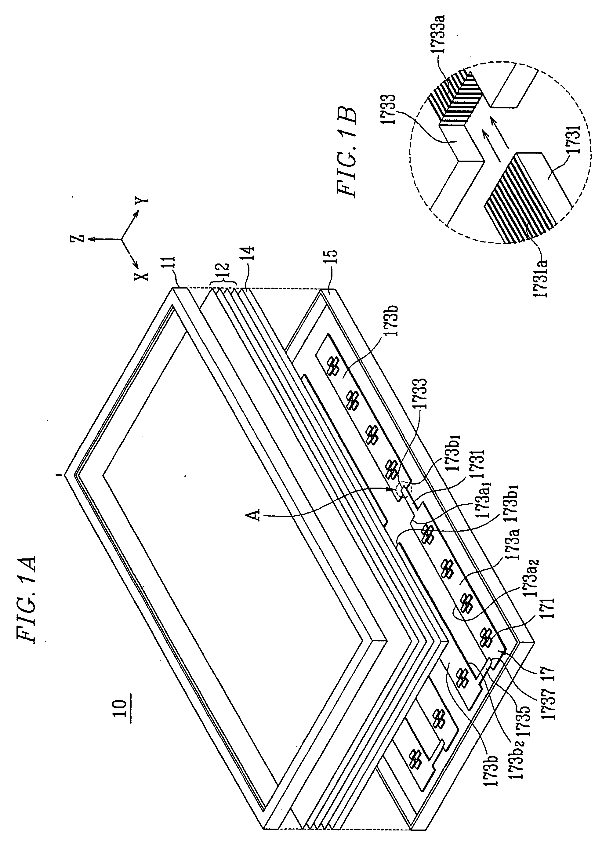
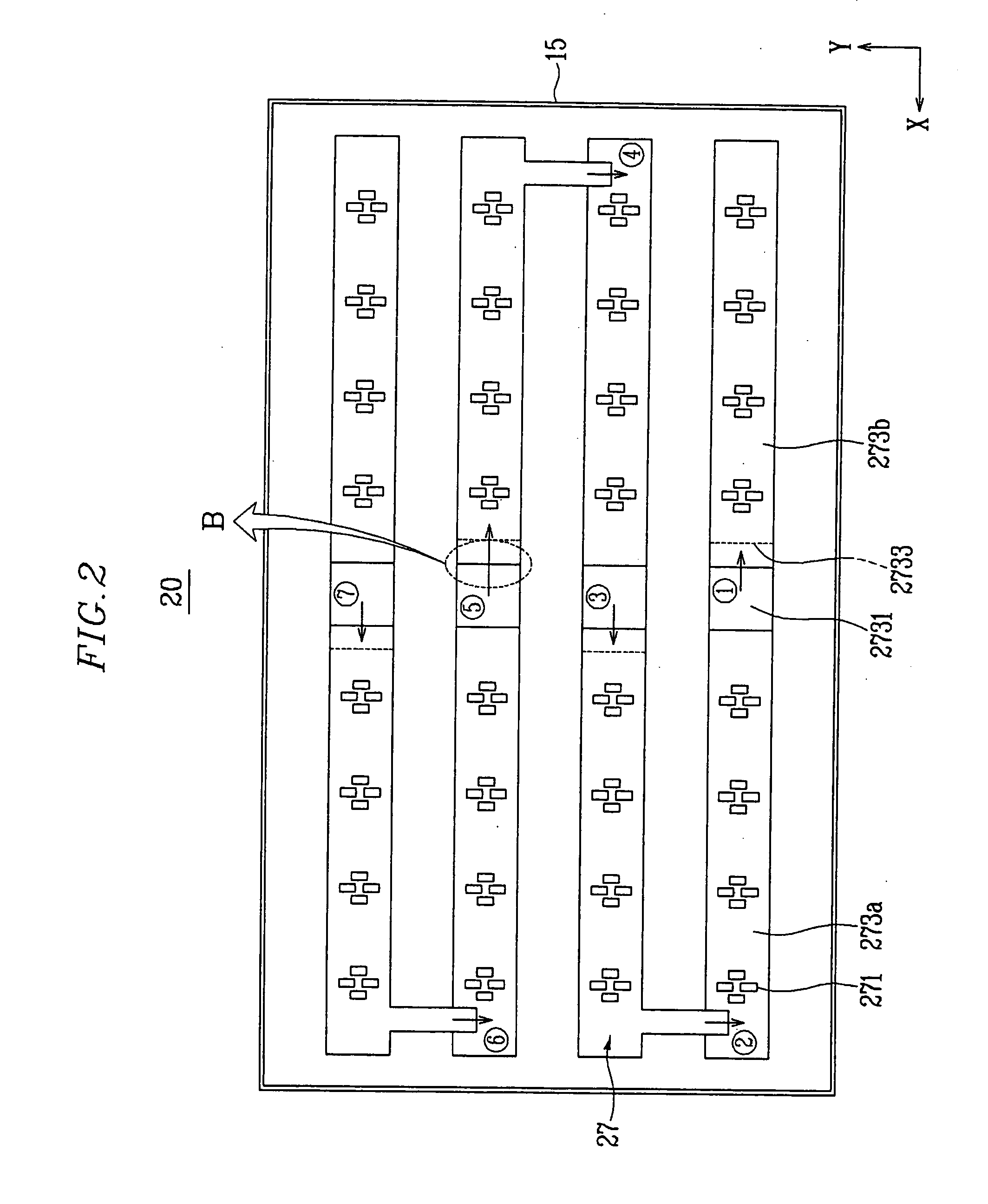
[0012] The present invention provides a backlight assembly having an improved connection structure of a metal core printed circuit board (“PCB”).

Problems solved by technology

When the metal core PCBs are connected to each other with cables, performing a connection process is time consuming, and interconnection is complicated, so that it is difficult to assemble the backlight assembly.
In addition, rework for the backlight assembly is complicated, and, due to the connectors and cables, it is difficult to implement an entirely planarized light source.
Also, since the connectors and cables may deteriorate due to heat released from the light source, the performance of the backlight assembly is reduced.
Furthermore, due to the connectors and cables, it is impossible to effectively use the light emitting from the light source.

Method used


Image

  • Backlight assembly, display device having the same, and method thereof
  • Backlight assembly, display device having the same, and method thereof
  • Backlight assembly, display device having the same, and method thereof

Examples


Embodiment Construction

[0044] The invention will now be described more fully hereinafter with reference to the accompanying drawings, in which embodiments of the invention are shown. This invention may, however, be embodied in many different forms and should not be construed as limited to the embodiments set forth herein. Rather, these embodiments are provided so that this disclosure will be thorough and complete, and will fully convey the scope of the invention to those skilled in the art. Like reference numerals refer to like elements throughout.

[0045] It will be understood that when an element is referred to as being “on” another element, it can be directly on the other element or intervening elements may be present there between. In contrast, when an element is referred to as being “directly on” another element, there are no intervening elements present. As used herein, the term “and / or” includes any and all combinations of one or more of the associated listed items.

[0046] It will be understood that...


PUM


Abstract

A backlight assembly and a display device having the backlight assembly are provided where the backlight assembly includes a plurality of light sources for emitting light and a plurality of metal core printed circuit boards on which the light sources are mounted. The metal core printed circuit boards are directly connected to each other in predetermined regions to emit light in a surface direction. A method of assembling the backlight assembly is further provided.

Description

[0001] This application claims priority to Korean Patent Application No. 2005-0054002, filed on Jun. 22, 2005 and all the benefits accruing therefrom under 35 U.S.C. §119, and the contents of which in its entirety are herein incorporated by reference. BACKGROUND OF THE INVENTION [0002] (a) Field of the Invention [0003] The present invention relates to a backlight assembly, a display device having the backlight assembly, and a method therof, and more particularly, the present invention relates to a backlight assembly with an improved connection structure of a metal core printed circuit board (“PCB”), a display device having the backlight assembly, and a method of assembling the backlight assembly. [0004] (b) Description of the Related Art [0005] As semiconductor techniques are rapidly developed, demands for lightweight, compact display devices has increased. [0006] Examples of the display devices include liquid crystal display (“LCD”) devices, plasma display panel (“PDP”) devices, an...

Claims


Application Information

Patent Timeline
Patent Type & Authority Applications(United States)
IPC IPC(8): H05K1/11
CPCG02F1/133603G02F2001/133612H05K1/056H05K1/117H05K1/142H05K3/107H05K2203/167H05K2201/09172H05K2201/09827H05K2201/09845H05K2201/09981H05K2201/10106H05K2201/09145G02F1/133612G02F1/1335
Inventor KIM, GI-CHERLCHO, JOO-WOANLEE, SANG-GILCHO, DON-CHANLEE, SANG-YU
Owner SAMSUNG DISPLAY CO LTD
Why Eureka
Try Eureka