Particle-optical systems and arrangements and particle-optical components for such systems and arrangements

Active Publication Date: 2006-12-28
CARL ZEISS MICROSCOPY GMBH +1
View PDF20 Cites 91 Cited by
  • Summary
  • Abstract
  • Description
  • Claims
  • Application Information

AI Technical Summary

Benefits of technology

[0090] An objective lens is provided for imaging the focusing region or an intermediate image thereof onto an object positionable in an object plane of the arrangement. By imaging foci of the charged-particle beamlets onto the object it is possible to obtain beam spots of comparatively low diameters on the object.
[0091] Further, the apertures in the at least one aperture plate may be provided with diameters substantially greater than diameters of the beamlets in a region of the foci. Thus, it is possible to

Problems solved by technology

Such particle-optical element typically contributes to a

Method used


Image

  • Particle-optical systems and arrangements and particle-optical components for such systems and arrangements
  • Particle-optical systems and arrangements and particle-optical components for such systems and arrangements
  • Particle-optical systems and arrangements and particle-optical components for such systems and arrangements

Examples


Example

[0129] In the exemplary embodiments described below, components that are similar in function and structure are designated as far as possible by similar reference numerals. Therefore, to understand the features of the individual components of a specific embodiment, the descriptions of other embodiments and of the summary of the invention should be referred to.

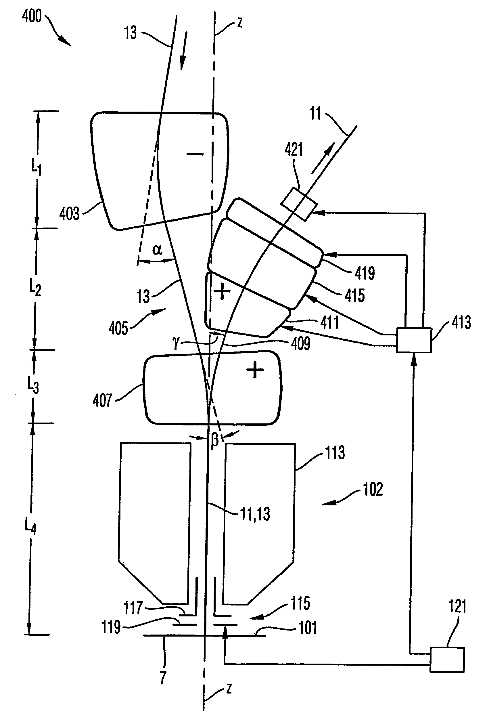
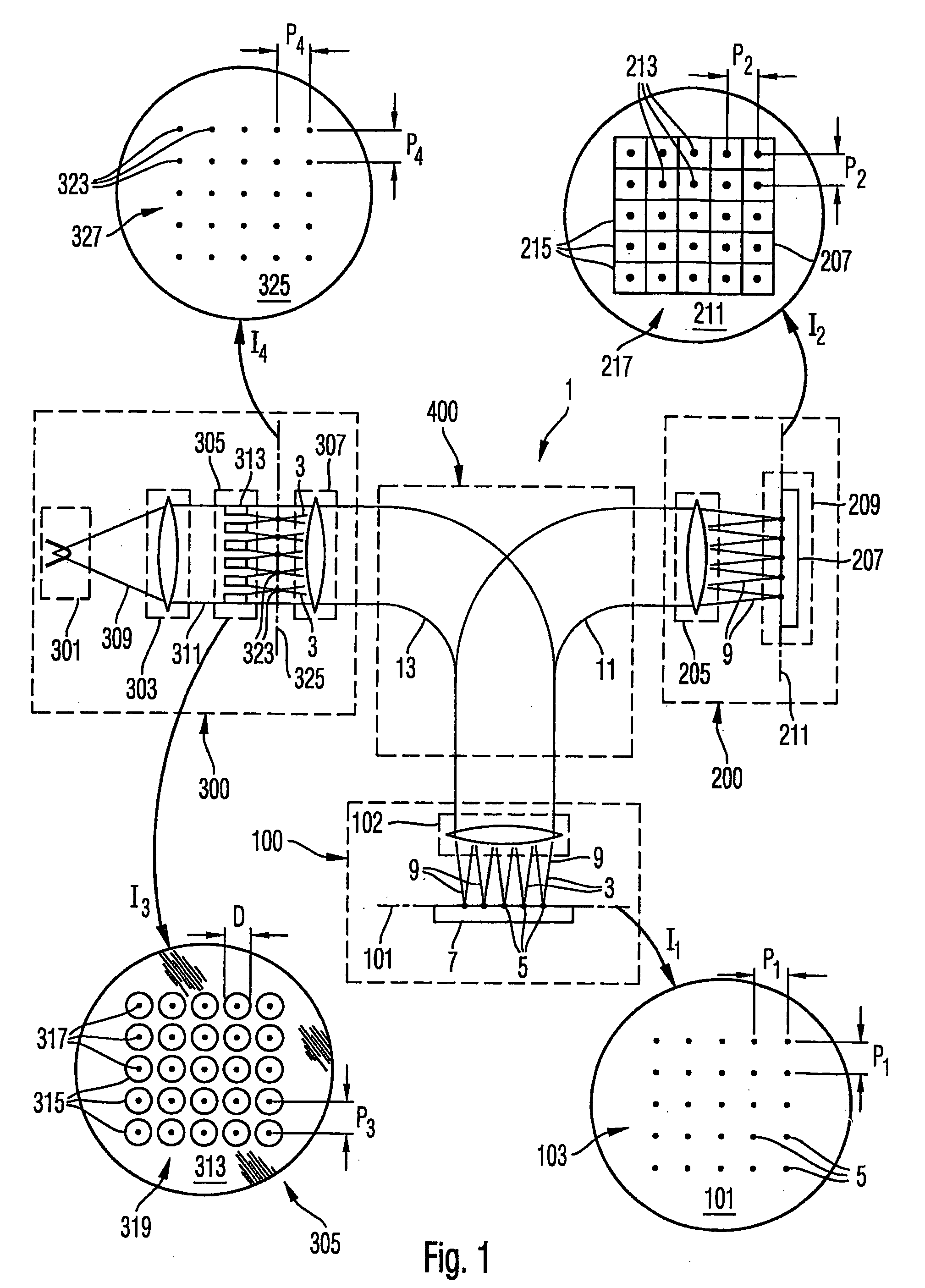
[0130]FIG. 1 is a schematic diagram symbolically illustrating basic functions and features of an electron microscopy system 1. The electron microscopy system 1 is of a scanning electron microscope type (SEM) using a plurality of primary electron beamlets 3 for generating primary electron beam spots 5 on a surface of an object 7 to be inspected which surface is arranged in an object plane 101 of an objective lens 102 of an objective arrangement 100.

[0131] Insert I1 of FIG. 1 shows an elevational view on object plane 101 with a regular rectangular array 103 of primary electron beam spots 5 formed thereon. In FIG. 1 a number of 2...


PUM


Abstract

An electron-optical arrangement provides a primary beam path for a beam of primary electrons and a secondary beam path for secondary electrons. The electron-optical arrangement includes a magnet arrangement having first, second and third magnetic field regions. The first magnetic field region is traversed by the primary beam path and the secondary beam path. The second magnetic field region is arranged in the primary beam path upstream of the first magnetic field region and is not traversed by the secondary beam path. The first and second magnetic field regions deflect the primary beam path in substantially opposite directions. The third magnetic field region is arranged in the secondary beam path downstream of the first magnetic field region and is not traversed by the first beam path. The first and third magnetic field regions deflect the secondary beam path in a substantially same direction.

Description

BACKGROUND OF THE INVENTION [0001] 1. Field of the Invention [0002] The invention relates to particle-optical systems using multiple beamlets of charged particles, such as an electron microscopy apparatus and electron lithography apparatus. [0003] Further the invention relates to particle-optical components and arrangements which may be used in particle-optical systems using multiple beamlets of charged particles; the particle-optical components are, however, not limited in the application to systems using multiple beamlets. Such particle-optical components may be used in particle-optical systems using only one single beam of charged particles or plural beams or beamlets of charged particles. [0004] The invention may be applied to charged particles of any type, such as electrons, positrons, myons, ions and others. [0005] 2. Brief Description of Related Art [0006] A conventional particle-optical system is known from U.S. Pat. No. 6,252,412 B1. The electron microscopy apparatus disclo...

Claims


Application Information

Patent Timeline
IPC IPC(8): G21K5/10H01JH01J37/09H01J37/153
CPCB82Y10/00H01J37/3007H01J37/09H01J37/28H01J37/3177H01J2237/0435H01J2237/0453H01J2237/2817H01J2237/31774H01J37/14H01J2237/047H01J2237/04735H01J2237/04756H01J2237/06H01J2237/14H01J37/10B82Y40/00H01J1/00H01J37/26H01L22/00H01J37/04H01J37/153
Inventor KNIPPELMEYER, RAINERKIENZLE, OLIVER
Owner CARL ZEISS MICROSCOPY GMBH
Why Eureka
Try Eureka