
Work fixing device

a technology for fixing devices and work, which is applied in the direction of chucks, mechanical equipment, manufacturing tools, etc., can solve the problems of inability to accurately fix work, affecting the working accuracy and operating efficiency, and affecting the stability of work, so as to achieve the effect of stably fixing a long work or a work to be worked, simplifying the working disc and the rotary drive mechanism

Inactive Publication Date: 2006-12-28
NIHON SPINDLE MFG CO LTD
View PDF9 Cites 12 Cited by
  • Summary
  • Abstract
  • Description
  • Claims
  • Application Information

AI Technical Summary

Benefits of technology

[0005] The objective of the present invention, realized in view of such problems of the above-described conventional work fixing device, is to provide a work fixing device capable of stably fixing the work, without any biasing, in the longitudinal direction of the work, of the fastening force for fixing the work.
[0025] Furthermore, by setting the interval of the clamps disposed on both sides of the working disc for a dimension larger than the diameter of the work, it becomes possible to stably fix a long work or a work to be worked at both ends.
[0026] Still more, by driving the scroll pieces disposed on both sides of the working disc in linkage with one another, it becomes possible to simplify the working disc and the rotary drive mechanism for it.
[0027] Yet more, by driving the scroll pieces disposed on both sides of the working disc independently of one another, it becomes possible to set the amount of movement of the clamps on both sides disposed on the scroll pieces independently for each side, and stably fix the work without any biasing, in the longitudinal direction of the work, of the fastening force for fixing the work, even in the case where the diameter is variable in the longitudinal direction or in the case of uneven works.

Problems solved by technology

However, with this arrangement, in which the clamp is supported and moved by the moving mechanism 3 disposed on either the back face or a side face of the clamp 2, the fixing of work was liable to be limited only to the central part of the work or biased to one side.
For that reason, in the case of a long work or a work of soft metal such as aluminum, etc. or a hollow work in tubular shape with small rigidity, or in the case where the dimensional accuracy is rather low and variable, there was a problem that the work cannot be fixed accurately, eventually having negative influences on the working accuracy and operating efficiency.

Method used


Image

  • Work fixing device
  • Work fixing device
  • Work fixing device

Examples


Embodiment Construction

[0039] Embodiments of the work fixing device according to the present invention will be described below, with reference to drawings.

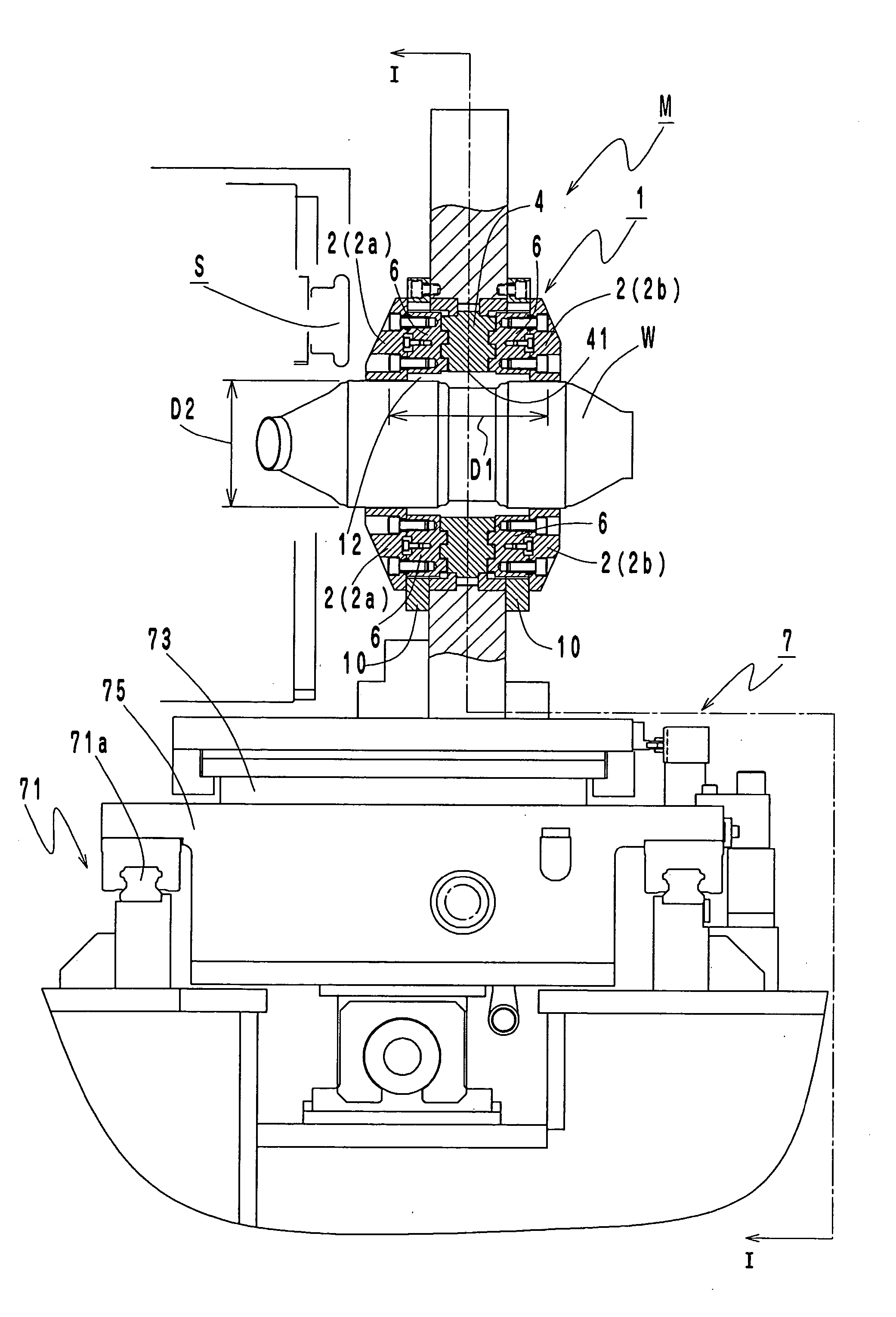
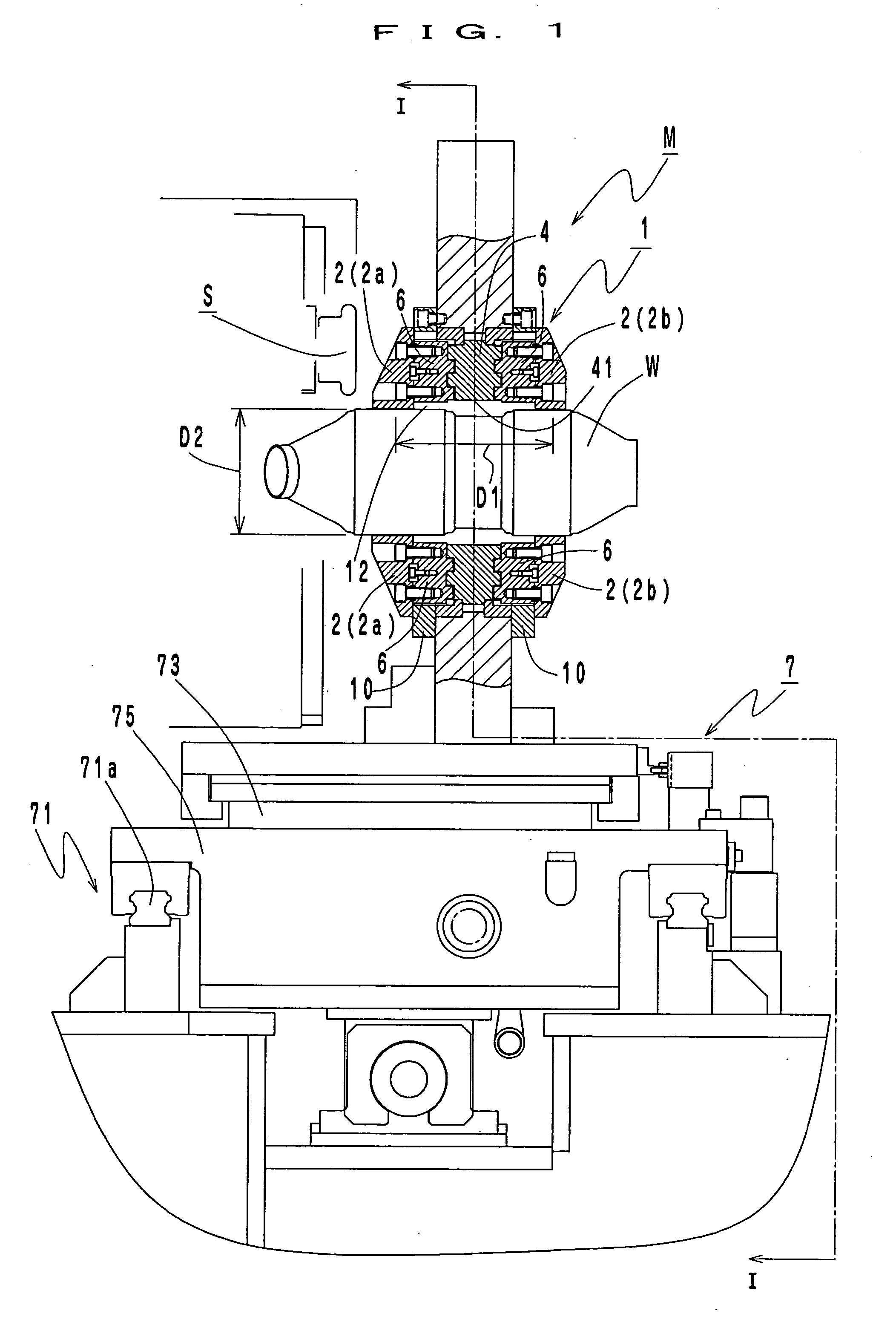
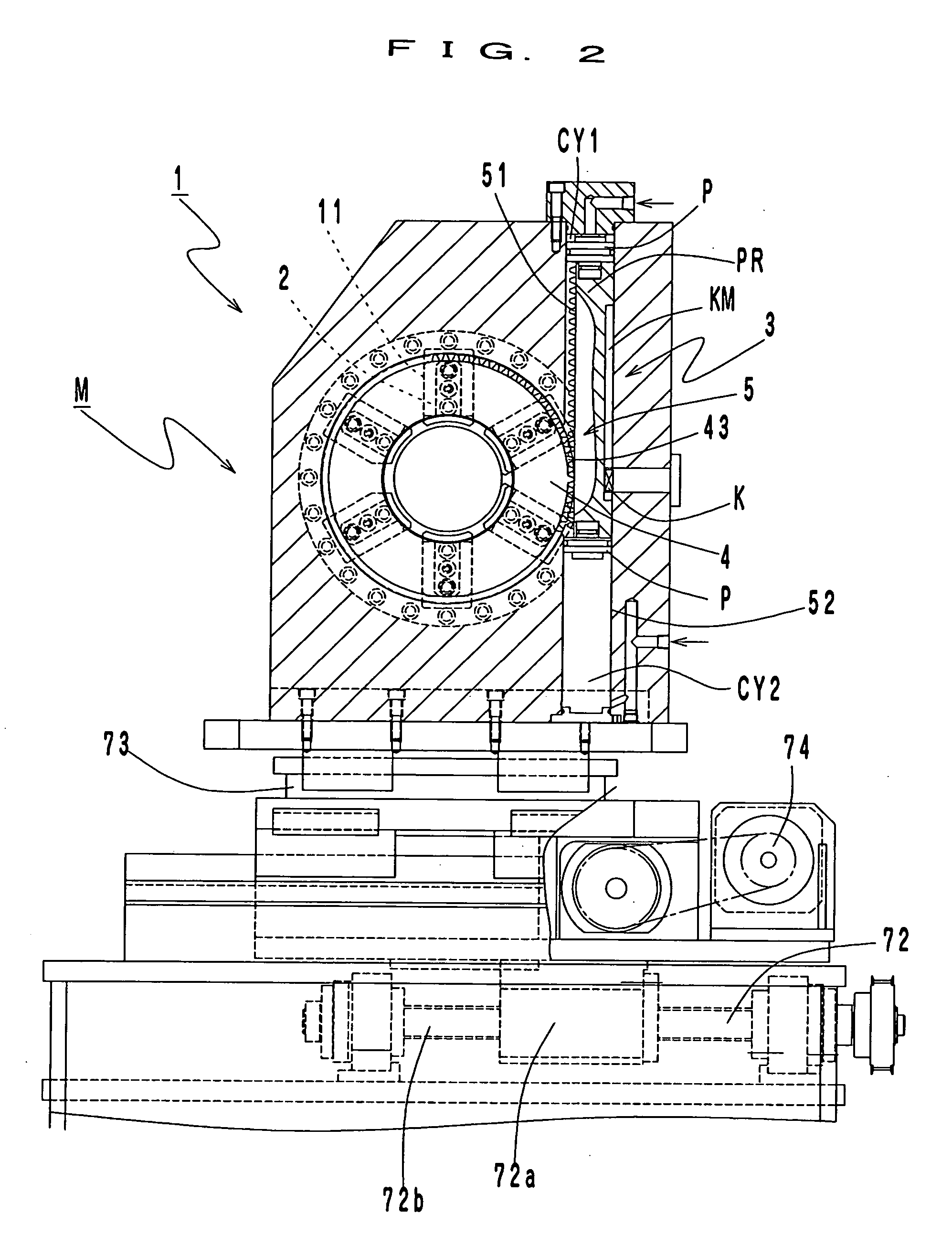
[0040]FIG. 1 to FIG. 7 show the first embodiment in which the work fixing device according to the present invention is applied to a device for executing spinning on a work.

[0041] This work fixing device M is disposed in a way to face a spinning system S for executing drawing by spinning at both ends of the work W, which is, in this embodiment, a hollow work in tubular shape with a circular section forming a constriction in the intermediate part.

[0042] And, the work fixing device M, designed for gripping the work W with circular section inserted in a circular hole 12 formed on the main body 1 of work fixing device, comprises a plurality of clamps 2 disposed movably along a guide groove 11 formed in the radial direction in the main body 1 of the work fixing device, and a clamp 2 moving mechanism 3 for synchronously moving the plurality of clamps 2 in t...


PUM


Abstract

The present invention provides a work fixing device capable of stably fixing the work, without any biasing, in the longitudinal direction of the work, of the fastening force for fixing the work. The moving mechanism 3 of clamps 2 is constructed by comprising a scroll disc 4 as working disc forming a circular hole 41 in which to insert the work W at the center and scroll guides 42a, 42b in spiral shape the winding direction of which is opposite to each other from the center toward the outer circumference on the both side faces, a rotary drive mechanism 5 for rotatably driving this scroll disc 4, and scroll pieces 6 having a fitting portion 61 to be engaged with the scroll guides 42a, 42b of the scroll disc 4 and disposed on both sides of the scroll disc 4 in a way to correspond to a plurality of clamps 2 respectively.

Description

BACKGROUND OF THE INVENTION [0001] The present invention relates to a work fixing device, more specifically a work fixing device for gripping a work with circular section inserted in a hole formed in the main body of the work fixing device, comprising a plurality of clamps disposed movably along a guide groove formed in the radial direction in the main body of the work fixing device; and a clamp moving mechanism for synchronously moving the plurality of clamps in the radial direction. [0002] Conventionally, when executing processing such as spinning, cutting, etc. on works with circular section (also including hollow works in tubular shape, in this specification), a variety of work fixing devices are used (JP 07-227733 A, for example), because of the necessity of fixing the work. [0003] By the way, this type of work fixing device usually comprises, as shown in FIG. 11, a clamp moving mechanism 3 for moving a plurality of clamps 2. However, with this arrangement, in which the clamp i...

Claims


Application Information

Patent Timeline
Patent Type & Authority Applications(United States)
IPC IPC(8): B23Q3/00
CPCB23B31/16004Y10T279/1926B23Q3/067
Inventor MURATA, SHIGEOHATA, NAOTOTAKADA, YOSHIAKI
Owner NIHON SPINDLE MFG CO LTD
Learn More