Capacitor Pulse Forming Network with Multiple Pulse Inductors

a technology of inductors and capacitors, applied in pulse train generators, secondary cells, pulse techniques, etc., can solve the problems of increasing the mass and size of the pulse forming network, not accurately tracking the desired flat top waveform, and increasing the flux generated by the inductors, so as to improve the pulse shaping characteristics, reduce the mass, and reduce the inductance

Inactive Publication Date: 2006-12-28
GENERAL ATOMICS
View PDF34 Cites 32 Cited by
  • Summary
  • Abstract
  • Description
  • Claims
  • Application Information

AI Technical Summary

Benefits of technology

[0009] The invention provides a capacitor based pulse forming network in which fewer inductors are pulsed more frequently to provide a smaller

Problems solved by technology

Furthermore, the waveform 208 does not accurately track the desired flat top waveform 201, especially at the end of the waveform.
Requiring many large inductors and needing

Method used


Image

  • Capacitor Pulse Forming Network with Multiple Pulse Inductors
  • Capacitor Pulse Forming Network with Multiple Pulse Inductors
  • Capacitor Pulse Forming Network with Multiple Pulse Inductors

Examples


Embodiment Construction

[0029] The following description is not to be taken in a limiting sense, but is made merely for the purpose of describing the general principles of the preferred embodiments. The scope of the invention should be determined with reference to the claims.

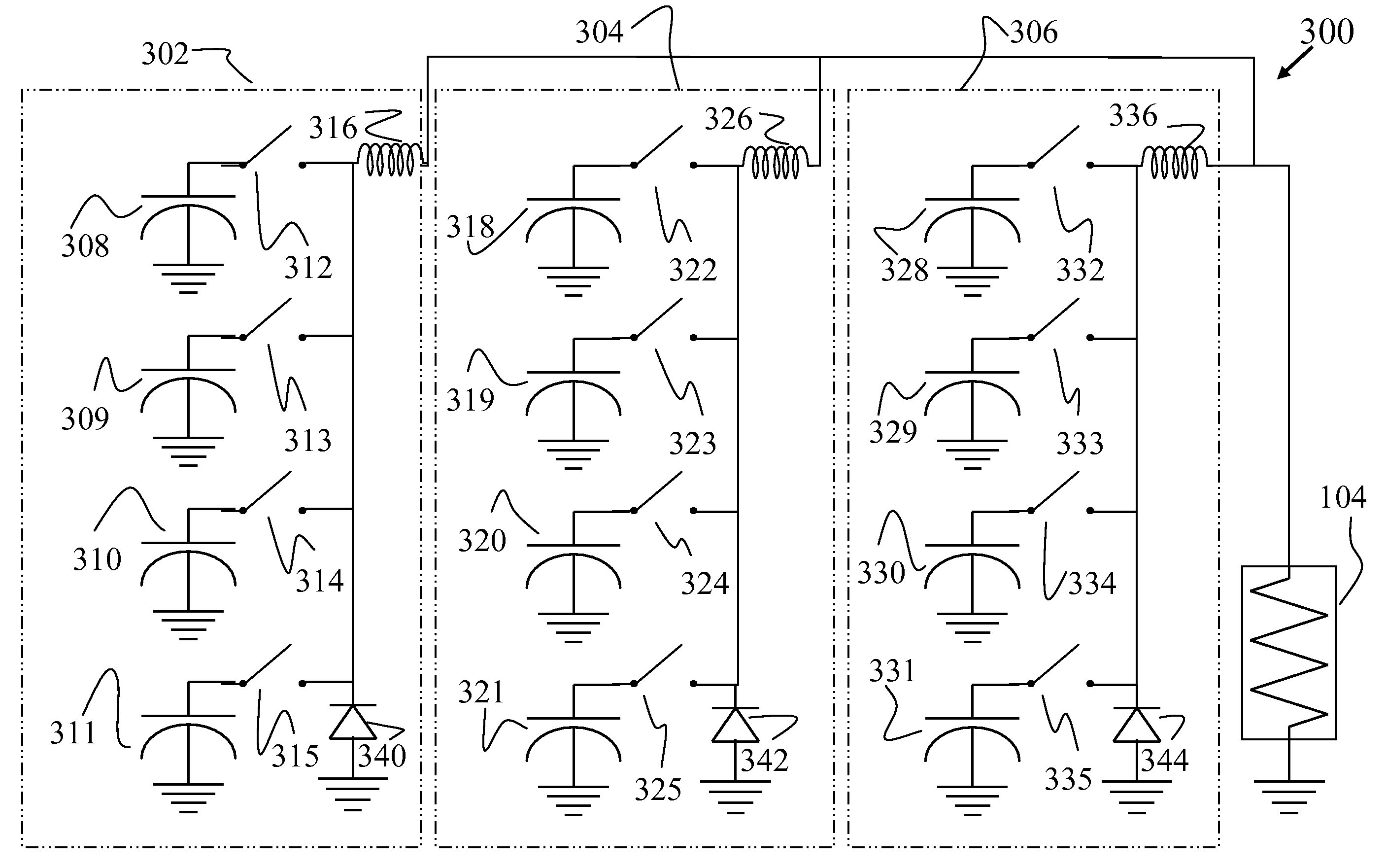
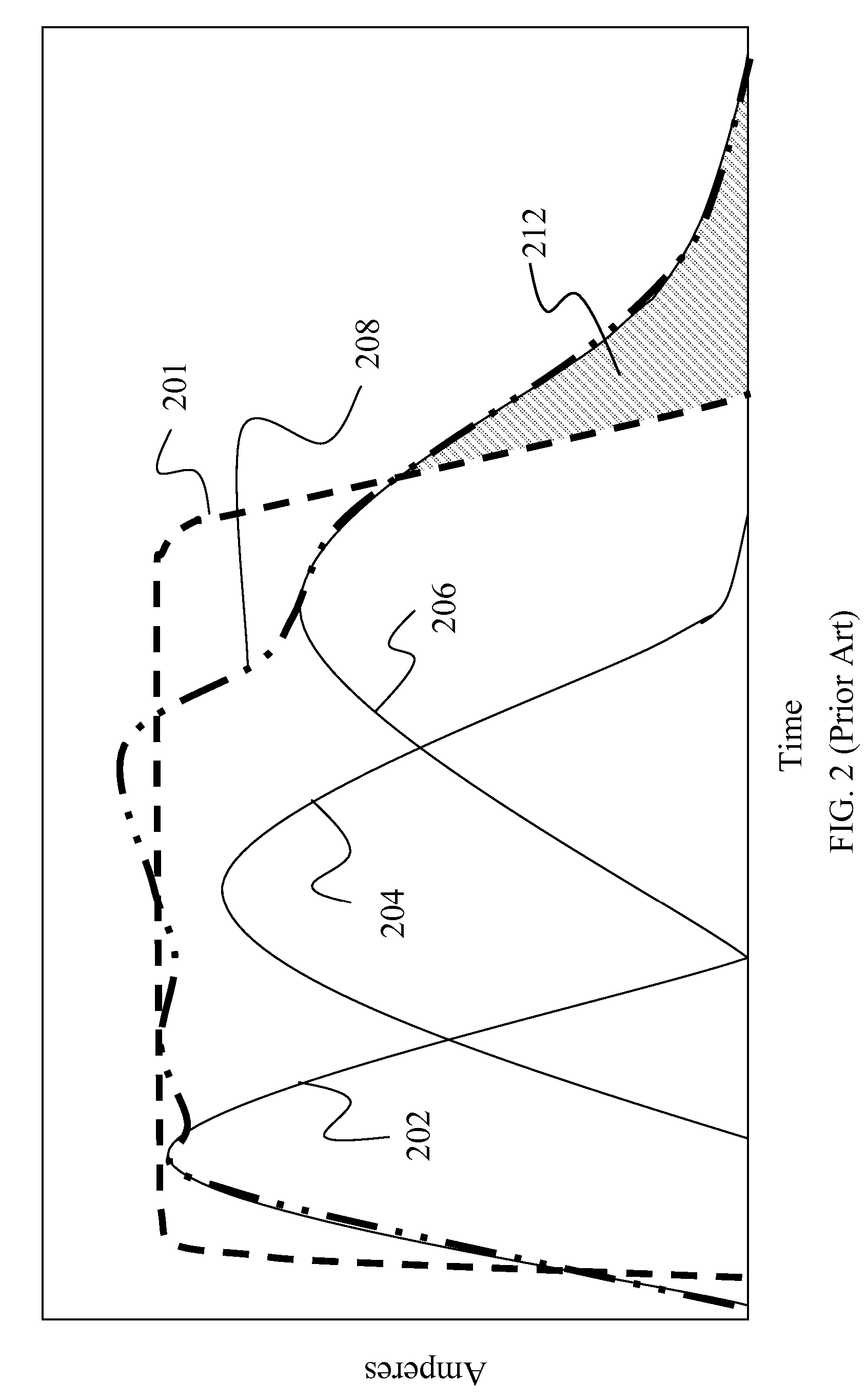
[0030] Referring first to FIG. 3, a diagram is shown of a pulse forming network according to one embodiment of the invention. Referring also to FIG. 4, a graph is shown illustrating an output pulse waveform produced by one embodiment of the pulse forming network of FIG. 3.

[0031] The pulse forming network 300 includes multiple capacitor units being switched through each inductor. Specifically, the pulse forming network 300 includes a plurality (e.g., three) energy storage modules 302, 304, 306 each coupled to a load 104. Each module 302, 304 and 306 includes a plurality (e.g., four) of capacitor units coupled to the load 104 through an inductor via a switch. Each module 302, 304, 306 also includes an anti-reversing diode (although in ...


PUM


Abstract

Capacitor based pulse forming networks and methods are provided which require fewer inductors are that pulsed more frequently to provide a smaller, lower mass, and lower inductance pulse forming network having better pulse shaping characteristics than conventional pulse forming networks. In one implementation, the invention can be characterized as a capacitor based pulse forming network comprising a plurality of inductors adapted to be coupled to a load, a plurality of capacitor units, and a plurality of switches. Each switch couples a respective capacitor unit to a respective inductor, wherein multiple capacitor units are coupled to each inductor by separate switches. The plurality of switches are adapted to non-simultaneously discharge at least some of the multiple capacitor units to provide non-simultaneous pulses through a given inductor to the load and not through other inductors. The non-simultaneous pulses form at least a portion of an output pulse waveform to the load.

Description

[0001] This application is a continuation-in-part of U.S. application Ser. No. 11 / 274,060, filed Nov. 14, 2005, for CAPACITOR PULSE FORMING NETWORK WITH MULTIPLE PULSE INDUCTORS, which is a continuation of U.S. application Ser. No. 10 / 772,748, filed Feb. 4, 2004, for CAPACITOR PULSE FORMING NETWORK WITH MULTIPLE PULSE INDUCTORS, now U.S. Pat. No. 6,965,215, both of which are incorporated in their entirety herein by reference.BACKGROUND OF THE INVENTION [0002] 1. Field of the Invention [0003] The present invention relates generally to capacitor-based high energy pulse forming networks. [0004] 2. Discussion of the Related Art [0005] In certain applications where high power sources (e.g., power lines, batteries) are unable to deliver high levels of peak power, pulse forming networks having high-energy density capacitors are often used. In these applications, the capacitors are slowly charged from the power source and then quickly discharged for short time periods to provide pulsed ener...

Claims


Application Information

Patent Timeline
IPC IPC(8): H03K3/00H01M10/44H01M10/46H02J1/00H03K3/53
CPCH03K3/53H02J1/00Y02E60/10H03K3/00H01M10/44H01M10/46
Inventor MACDOUGALL, FREDERICK W.STAINES, GEOFFREY W.
Owner GENERAL ATOMICS
Why Eureka
Try Eureka