Diagnostic radio frequency identification sensors and applications thereof

a radio frequency identification and sensor technology, applied in the field of diagnostics, can solve the problems of inability of rfid readers to communicate through multiple protocols, inability of conventional rfid readers to automatically update or change protocols, and current rfid readers to communicate with rfid tags having a communication protocol, etc., to achieve low cost, low cost, low cost

Active Publication Date: 2006-12-28
ALTIVERA
View PDF43 Cites 469 Cited by
  • Summary
  • Abstract
  • Description
  • Claims
  • Application Information

AI Technical Summary

Benefits of technology

[0007] This invention is directed to a system and method for low cost wireless diagnostics using modified radio frequency identification (RFID) tags that are combined with novel types of diagnostic sensors. A further aspect of this invention is that the diagnostic sensors can be read and analyzed on the spot by low cost wireless devices such as modified cell phones that incorporate multi-protocol RFID reader and communication standards such as Gen-2. The technology allows a modified cell phone to be used to directly identify ext

Problems solved by technology

A first disadvantage includes the inability of a RFID reader to communicate through the use of multiple protocols.
Consequently, the conventional RFID readers are incapable of automatically updating or changing protocols.
Thus, the current RFID readers are unable to communicate with RFID tags having a comunication protocol that differs from the RFID reader pre-programmed protocol.
A second disadvantage includes the inability to conveniently monitor objects containing the RFID tag from virtually any location.
A third disadvantage of c

Method used


Image

  • Diagnostic radio frequency identification sensors and applications thereof
  • Diagnostic radio frequency identification sensors and applications thereof
  • Diagnostic radio frequency identification sensors and applications thereof

Examples


Embodiment Construction

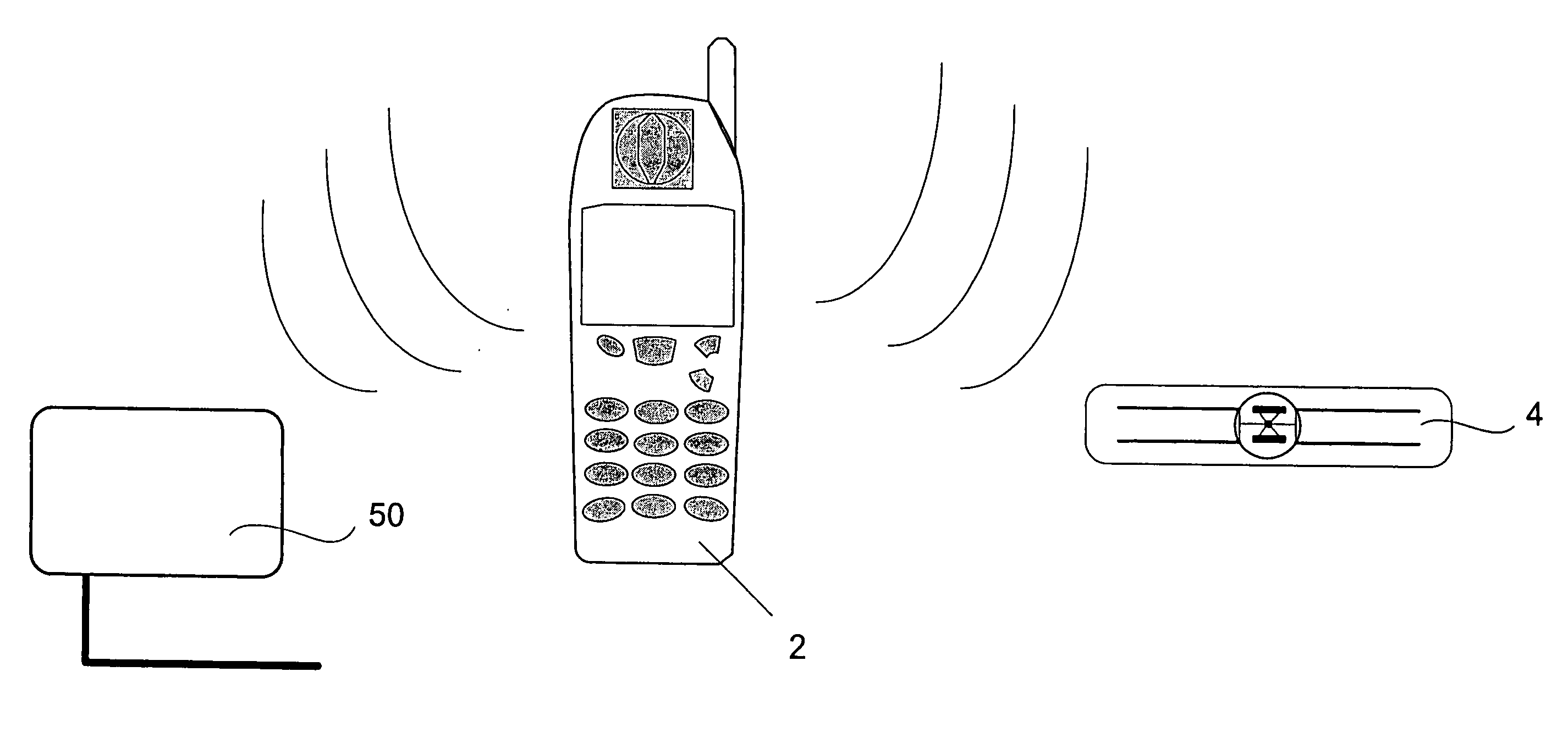
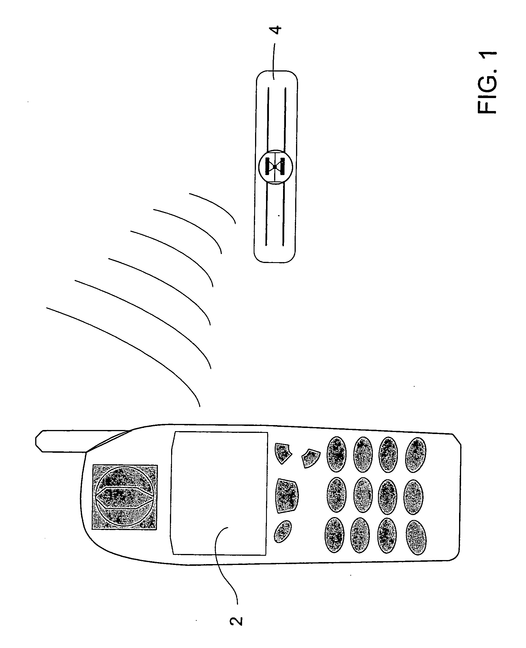
[0041] The technology described herein allows sensor technologies to be coupled to radio frequency identification (RFID) tags that provide both the power and the wireless interface for the sensor at very low cost. Another aspect of this invention is that common wireless devices such as cell phones can be modified to include the necessary logic and components to become RFID readers. The reader device can furthermore include a multi-protocol RFID reader capability, making it a universal reader for any RFID EPC tag or RFID-sensor tag, regardless of the manufacturer. This technology combination allows on the spot sophisticated processing of complex sensor data at a relatively low cost. The technology also allows RFID tags or sensor tags to be accessed by the Internet using the wireless reader device as a sensor communication tool. Identification retrieval and on the spot software download into the reader therefore becomes possible. Using this dual technology approach, almost any type of...


PUM


Abstract

An integrated passive wireless chip diagnostic sensor system is described that can be interrogated remotely with a wireless device such as a modified cell phone incorporating multi-protocol RFID reader capabilities (such as the emerging Gen-2 standard) or Bluetooth, providing universal easy to use, low cost and immediate quantitative analyses, geolocation and sensor networking capabilities to users of the technology. The present invention can be integrated into various diagnostic platforms and is applicable for use with low power sensors such as thin films, MEMS, electrochemical, thermal, resistive, nano or microfluidic sensor technologies. Applications of the present invention include on-the-spot medical and self-diagnostics on smart skin patches, Point of Care (POC) analyses, food diagnostics, pathogen detection, disease-specific wireless biomarker detection, remote structural stresses detection and sensor networks for industrial or Homeland Security using low cost wireless devices such as modified cell phones.

Description

CROSS REFERENCE TO RELATED APPLICATIONS [0001] This application claims priority to U.S. Provisional Application 60 / 539,419, filed on Jan. 27, 2004, which is incorporated herein by reference in its entirety.TECHNICAL FIELD [0002] The present invention generally relates to radio frequency identification (RFID) tags, and more specifically to a system having RFID tags that include diagnostic sensors, wherein the RFID tag and sensor are accessible by a wireless device such as a modified cell phone with a multi-protocol reader capability. BACKGROUND[0003] The conventional radio frequency identification (RFID) tag systems include an RFID tag that transmits data for reception by an RFID reader (also referred to as an interrogator). In a typical RFID system, individual objects (e.g., store merchandise) are equipped with a relatively small tag that contains a transponder. The transponder has a memory chip that is given a unique electronic product code. The RFID reader emits a signal activatin...

Claims


Application Information

Patent Timeline
IPC IPC(8): G08B13/14A61B5/00A61B5/02A61B5/145C12M3/00C12Q1/00G01N33/543G01N33/58G08B1/08G08B21/00G08B23/00G08C15/00H04B7/00H04M1/72412
CPCA61B5/0002A61B2560/0285A61B5/02A61B5/1112A61B5/1411A61B5/14532A61B5/14546A61B5/1491A61B5/411A61B5/4839A61B2560/0242A61B2560/0412A61B2560/0462A61B2562/08A62B99/00G01D21/00G01K13/00G01N33/54373G01N33/5438G01N33/58G01N35/00871G01N2035/00881G06K19/0717G08B31/00H04M1/7253H04M2250/02H04W64/00H04W80/00H04W84/18H04W88/02H04W88/06G06K19/0723A61B5/14514A61B5/6832A61B5/0008A61B5/150022A61B5/150358A61B5/150793A61B5/150854A61B5/15087A61B5/150969A61B5/150984A61B5/157G01N33/12G01N33/146Y02A30/00H04M1/72412G01N33/543A61B5/00G06K17/00B01L2300/0825B01L2300/0819B01L2300/0816B01L2300/08A61B90/98A61B5/02028A61B5/6833
Inventor PEETERS, JOHN P.
Owner ALTIVERA
Why Eureka
Try Eureka