Lens array optical system, projection optical unit, and image projection apparatus

a technology of optical array and lens array, applied in the field of optical systems, can solve the problems of affecting the image quality, and affecting the use efficiency of the lens array, and achieve the effects of reducing the light angular distribution, and easy molding of the lens array

Active Publication Date: 2006-12-28
CANON KK
View PDF19 Cites 21 Cited by
  • Summary
  • Abstract
  • Description
  • Claims
  • Application Information

AI Technical Summary

Benefits of technology

[0011] The present invention is directed to an optical system that provides high light use efficiency b

Problems solved by technology

Therefore, use of an optical element that has a characteristic or incident angle dependency sensitive to an angular distribution of the incident light in the illumination optical system would pose problems of the uneven brightness and color, the lowed contrast, and the deteriorated image quality.

Method used


Image

  • Lens array optical system, projection optical unit, and image projection apparatus
  • Lens array optical system, projection optical unit, and image projection apparatus
  • Lens array optical system, projection optical unit, and image projection apparatus

Examples


first embodiment

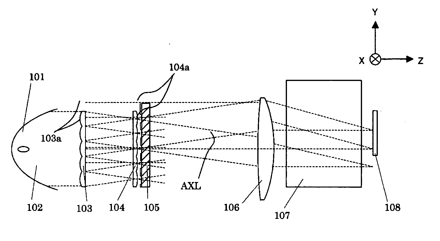
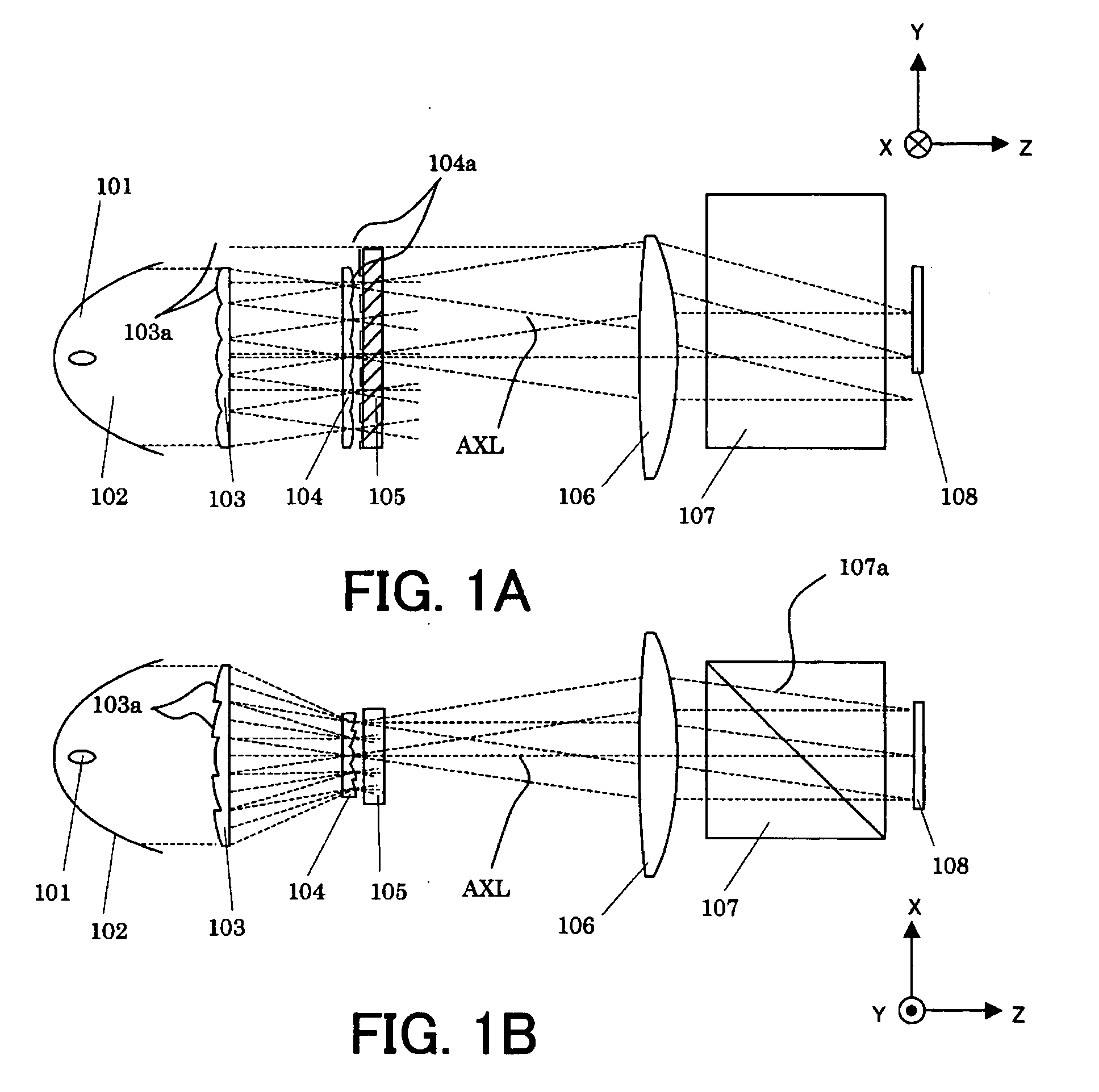
[0033]FIGS. 1A and 1B show a structure of an illumination optical system according to a first embodiment of the present invention. Here, an illumination optical system in a projector uses a reflection-type liquid crystal panel ((reflective liquid crystal panel) as an image modulation element or image forming element. The present invention is applicable to an illumination optical system of the projector using the transmission type liquid crystal panel.

[0034]FIGS. 1A and 1B indicate a section having a wide light angular distribution (YZ section: second section) and a narrow light angular distribution (YZ section: first section), where Z-axis is an axis that extends along a central optical axis AXL of the illumination optical system (which is an optical axis that passes the center of the illumination optical system). FIGS. 1A and 1B show only basic components in the illumination optical system for description convenience. Indeed, the illumination optical system further includes other ...

second embodiment

[0057]FIG. 7 schematically shows the XZ section of the first lens cell 203a most distant from the central optical axis AXL in the first lens array 203 in the illumination optical system according to a second embodiment of the present invention. Although the entire illumination optical system is not shown, this embodiment has a basic structure similar to the illumination optical system of the first embodiment. This embodiment also satisfies Equation (2).

[0058] In this embodiment, a shape of the first lens cell 203a is an aspheric surface AS on the XZ section most distant from the central optical axis AXL. In FIG. 7, C denotes a spherical surface having the same apex as the aspheric surface AS, and a predetermined radius of curvature.

[0059] An aspheric surface AS of the first lens cell 203a on the XZ section may correct or mitigate the spherical aberration that would significantly occur when the first lens cell 203 uses a spherical surface C. A light source image that maintains its ...

third embodiment

[0062]FIGS. 8A and 8B show an illumination optical system according to a third embodiment of the present invention. This embodiment also shows an illumination optical system in a projector that uses a reflection-type liquid crystal panel 308 as an image modulation element (or an image forming element). FIGS. 8A and 8B indicate the YZ and XZ sections, respectively.

[0063] The elements in the illumination optical system of this embodiment includes, similar to the first embodiment, a light source 301, a paraboloid reflector 302, a first lens array 303, a second lens array 304, a polarization conversion element 305, a condenser lens 306, and a polarization beam splitter (not shown) between the condenser lens 306 and the reflection-type liquid crystal panel 308.

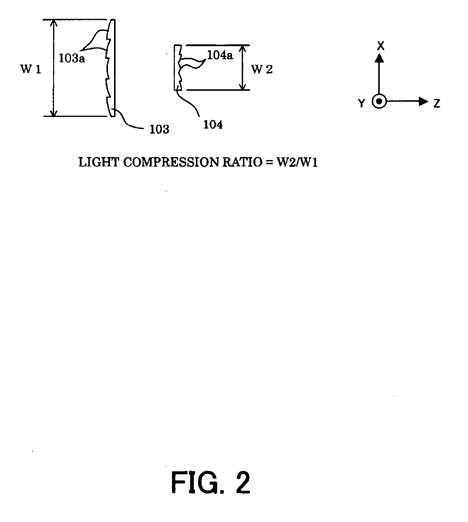
[0064] This embodiment sets a light compression ratio W2 / W1 greater than 1 on the XZ section, and an arrangement area width of the second lens cell 304a in the second lens array 304 wider than an arrangement area width of the fir...


PUM


Abstract

A lens array optical system includes a first lens array that includes plural first lens cells arranged in first and second directions, the first lens array being configured to split a light flux to plural split light fluxes and to condense each split flux; and a second lens array that includes plural second lens cells arranged in the first and second directions, each second lens cell being configured to receive the split lights from each first lens cell, wherein a ratio between a width of an arrangement area of the first lens cells and a width of an arrangement area of the second lens cells in the first direction is different from a ratio between a width of an arrangement area of the first lens cells and a width of an arrangement area of the second lens cells in the second direction, and wherein at least one of the first and second lens arrays has a toric surface.

Description

BACKGROUND OF THE INVENTION [0001] The present invention is an optical system having a lens array that includes plural, two-dimensionally arranged lens cells, and is used, for example, for an optical system used to illuminate the image modulation element or image forming element using a light from a light source. [0002] A conventional projector or image projecting apparatus modulates a light from a light source by using an image modulation element, such as a liquid crystal panel, in accordance with an image signal, and projects the modulated light onto a screen via a projection lens. It is important for this projector to maintain uniform brightness and color and a high contrast on an image projected on a screen. [0003]FIGS. 11A and 11B show an illustrative illumination optical system that illuminates an image modulation element in the projector. FIGS. 11A and 11B show an YZ section and an XZ section in the conventional illumination optical system. The Z-axis is an axis that extends ...

Claims


Application Information

Patent Timeline
IPC IPC(8): G03B21/20
CPCG03B21/208G02B27/0961
Inventor INOKO, KAZUHIROKODAMA, HIROYUKI
Owner CANON KK
Why Eureka
Try Eureka