

Method for the calibration of a distance image sensor
a technology of distance image sensor and calibration method, which is applied in the direction of distance measurement, instruments, and reradiation, can solve the problems of corresponding problems when using video sensors, and the alignment of the distance image sensor relative to the vehicle does not meet the specification, and achieves good accuracy.
- Summary
- Abstract
- Description
- Claims
- Application Information
AI Technical Summary
Benefits of technology
Problems solved by technology
Method used
Image

Examples
first embodiment
[0125] In another embodiment the actual angle between a plane perpendicular to the xLS-yLS-plane of the laser scanner coordinate system in which the angle ε lies and the plane perpendicular to the x-y-plane of the vehicle coordinate system in which the angle β is determined are taken into account more precisely. For this purpose, starting values for the pitch angle and a roll angle are calculated starting from the value derived in accordance with the With these values the alignment of the plane in which the angle ε lies and of the plane perpendicular to the x-y-plane of the vehicle coordinate system in which the angle β is determined is then determined by means of known trigonometric relationships. With the known alignment the angle ε or β′ can now be determined to a first approximation. On this basis new values for the pitch angle and for the roll angle are found. The alignment can be determined very precisely by iteration, in which the values for the pitch angle and the roll angl...
third embodiment
[0136] In a third embodiment only two first calibration surfaces spaced apart from another transverse to the longitudinal axis of the vehicle are used which are respectively inclined in the same way as the first calibration surface 46″.
[0137] For each of the first calibration surfaces 46″ the position of a reference point Pv in its z-direction of the vehicle coordinate system determined in accordance with the first embodiment can be found with a known preset distance D of the respective calibration surface 46″ from the laser scanner 14 (see FIG. 14). In the laser scanner coordinate system this point has the zLS-coordinate 0. The equation cos β=h0d-DHd B-HBsin β
[0138] applies, i.e. after the determination of β as in the first embodiment
z=h0+d·sin β.
[0139] Thus three points for the xLS-yLS-plane, the two reference points of the calibration surfaces and the origin of the laser scanner coordinate system are known so that the pitch angle and the roll angle can be determined fro...
fourth embodiment
[0140] In a fourth embodiment the distance image points in two scanned areas are used together with the just described calibration surfaces, whereby the inclination of the corresponding virtual beams relative to the surface 12 and from this the pitch angle and roll angle can be found.
Reference Numeral List
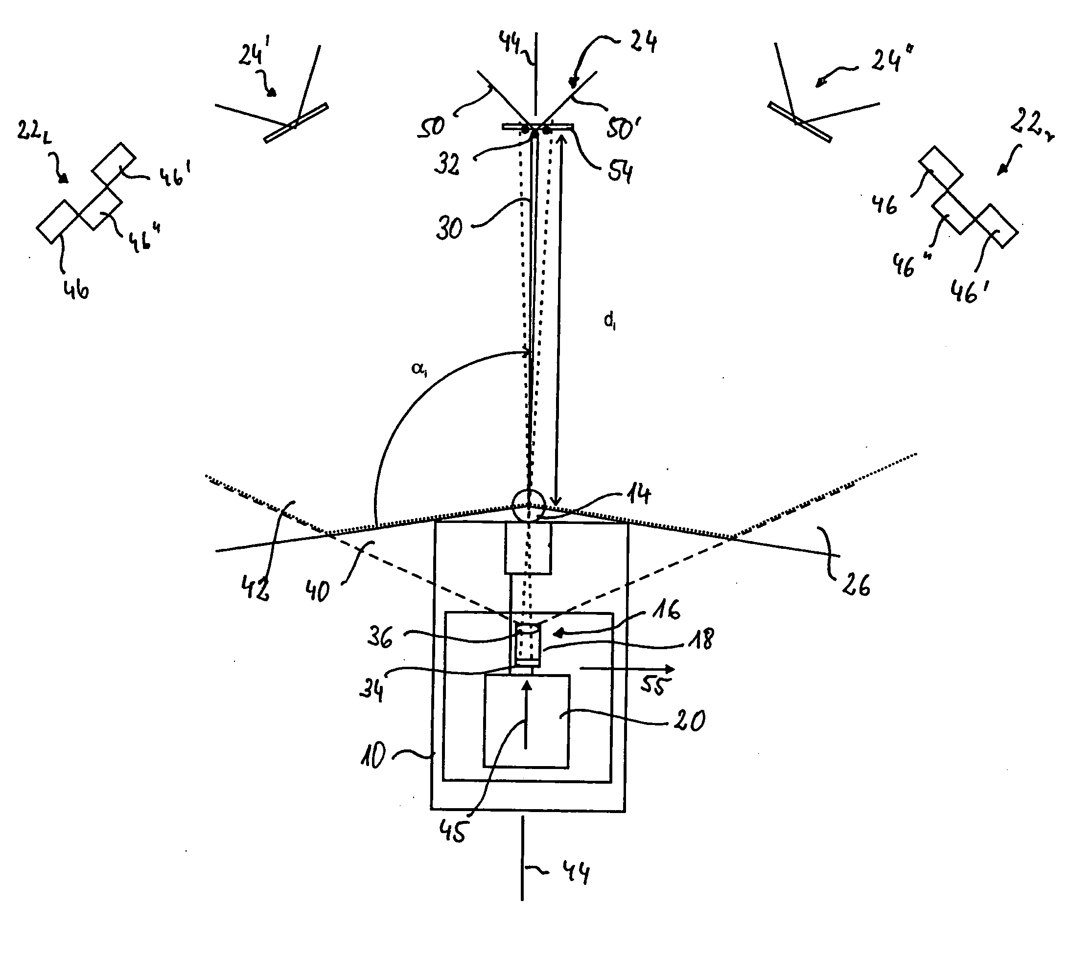
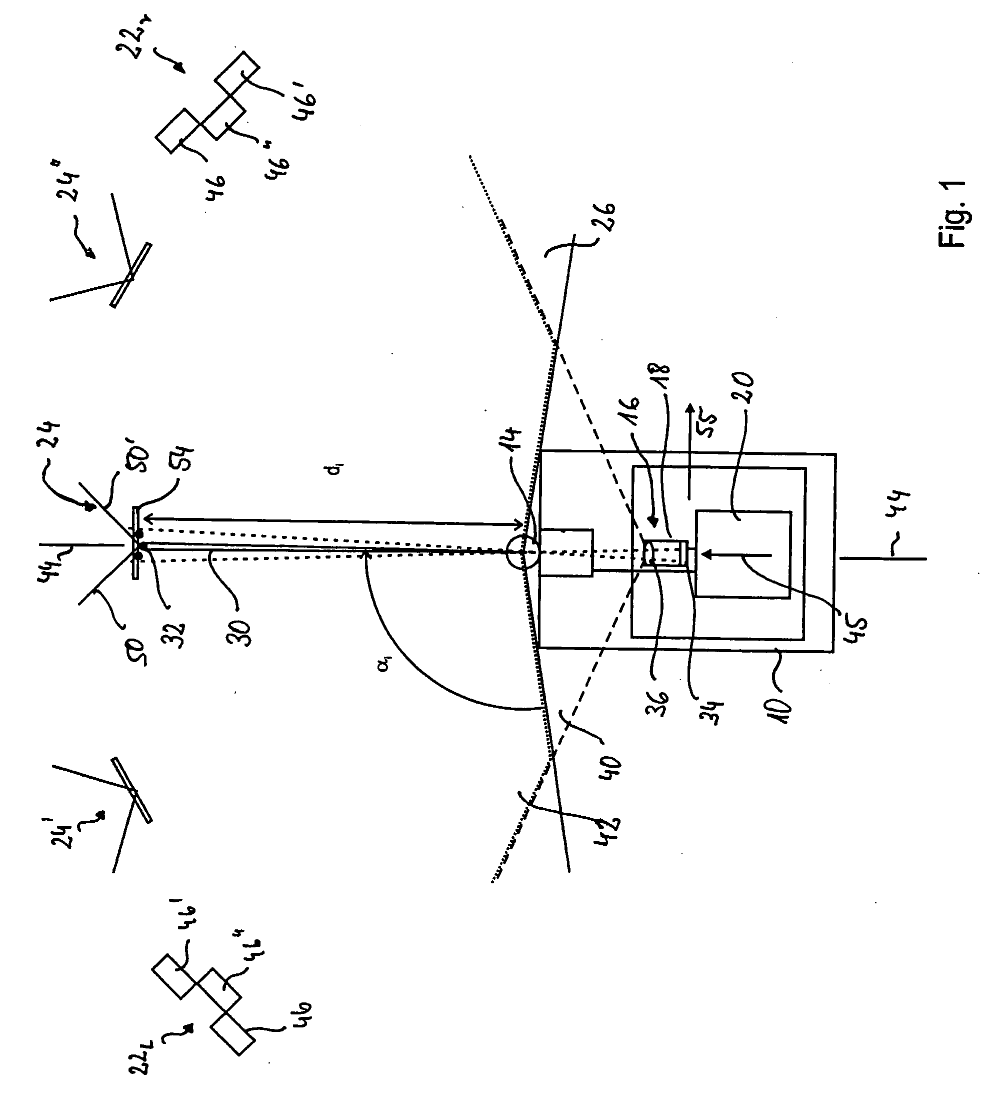
[0141]10 vehicle
[0142]12 surface
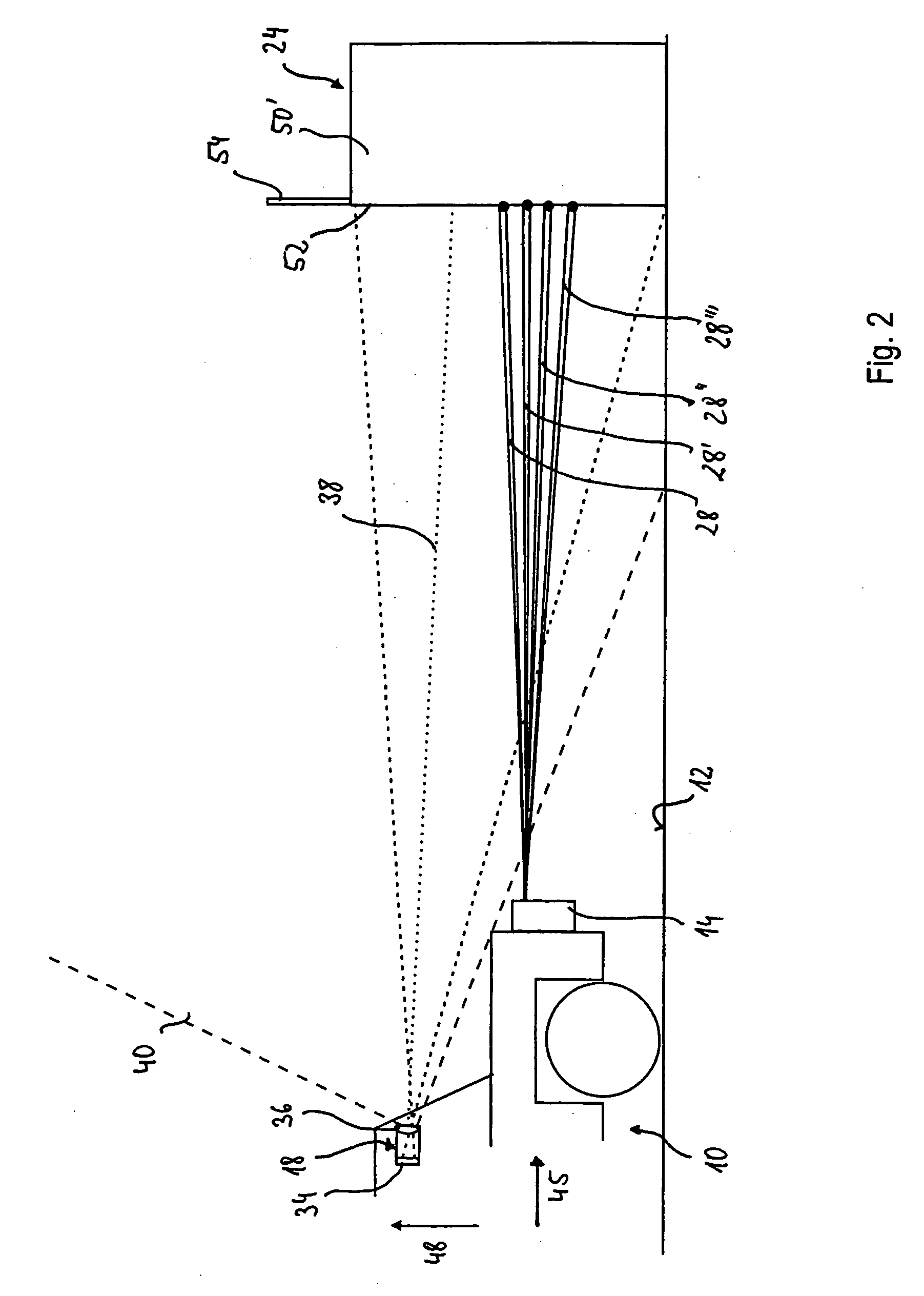
[0143]14 laser scanner
[0144]16 video system
[0145]18 video camera
[0146]20 date processing device
[0147]221, 22r first calibration objects
[0148]24, 24′, 24″ second calibration objects
[0149]26 detection range
[0150]28, 28′, 28″, 28′″ scanned areas
[0151]30 laser beam
[0152]32 object point
[0153]34 CCD-area sensor
[0154]36 image forming system
[0155]38 optical axis
[0156]40 video detection range
[0157]42 monitoring range
[0158]44 reference line
[0159]45 longitudinal axis of vehicle
[0160]46, 46′, 46″ first calibration surfaces
[0161]48 vertical axis of vehicle
[0162]50, 50′ second calibration surfaces
[0163]52 edge
[0164]54 third calibration surf...
PUM
 Abstract
Description
Claims
Application Information