Heat dissipation device

a heat dissipation device and electronic component technology, applied in the direction of electrical apparatus casings/cabinets/drawers, cooling/ventilation/heating modifications, instruments, etc., can solve the problems and achieve the effect of increasing the cost of components and dissipating hea

Inactive Publication Date: 2006-12-28
MICRO-STAR INTERNATIONAL
View PDF16 Cites 31 Cited by
  • Summary
  • Abstract
  • Description
  • Claims
  • Application Information

AI Technical Summary

Benefits of technology

[0010] The heat dissipation device provides an adjustable heat dissipation device for solving the problems of prior art that the assembling and detaching of the frame are inconvenient and an increase in the cost of components due to adopting buckle design.
[0011] The heat dissipation device for dissipating heat from a plug-in memory of a computer system provided by the present invention comprises a base frame, a moving frame, a retaining cover, and a heat dissipation fan. The base frame is disposed at one side of the memory socket and has a pair of wing plates, wherein the wing plates each have a guide slot. The moving frame is movably disposed in the guild slots. The retaining cover is movably disposed on the moving frame. The heat dissipation fan is mounted on the retaining cover to move along with the moving frame and the retaining cover, such that the heat dissipation fan has at least a retraction position where the heat dissipation fan is not overlaid above the memory so as to plug or remove the memory, and a heat dissipation position where the heat dissipation fan is above the memory to dissipate heat from the corresponding memory. Based on the moving relation between the moving frame and the retaining cover, different heat dissipation positions can be further obtained to provide the optimal heat dissipation mode in accordance with the actual heat dissipation requirements.

Problems solved by technology

The heat dissipation device provides an adjustable heat dissipation device for solving the problems of prior art that the assembling and detaching of the frame are inconvenient and an increase in the cost of components due to adopting buckle design.

Method used


Image

  • Heat dissipation device
  • Heat dissipation device
  • Heat dissipation device

Examples


first embodiment

The First Embodiment

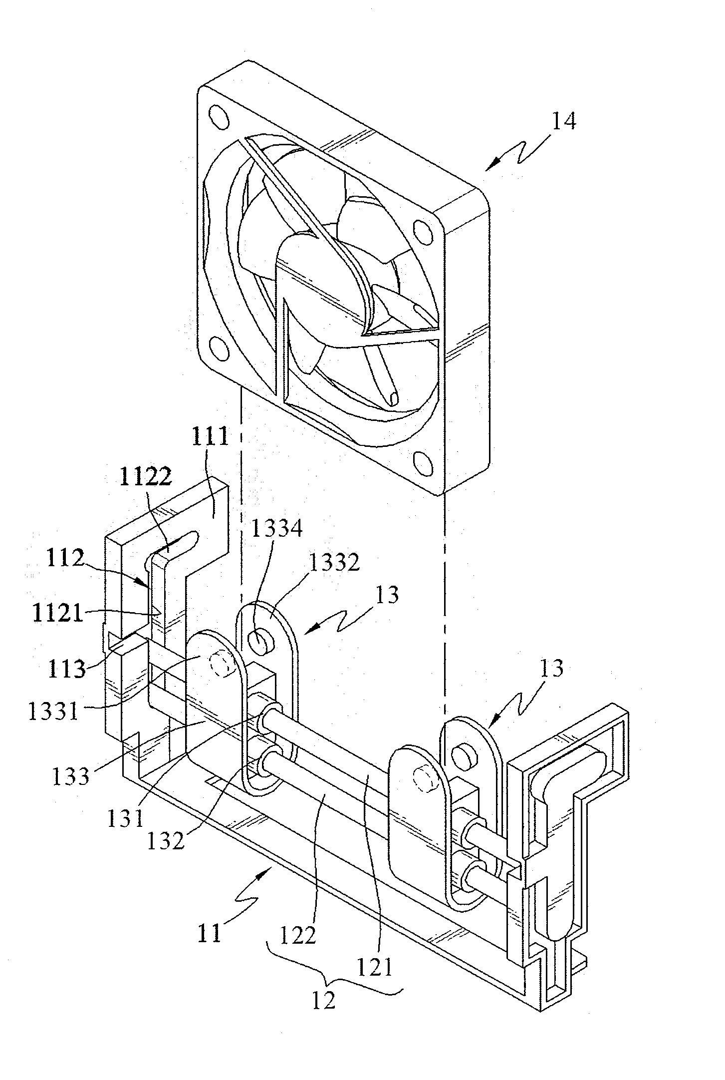
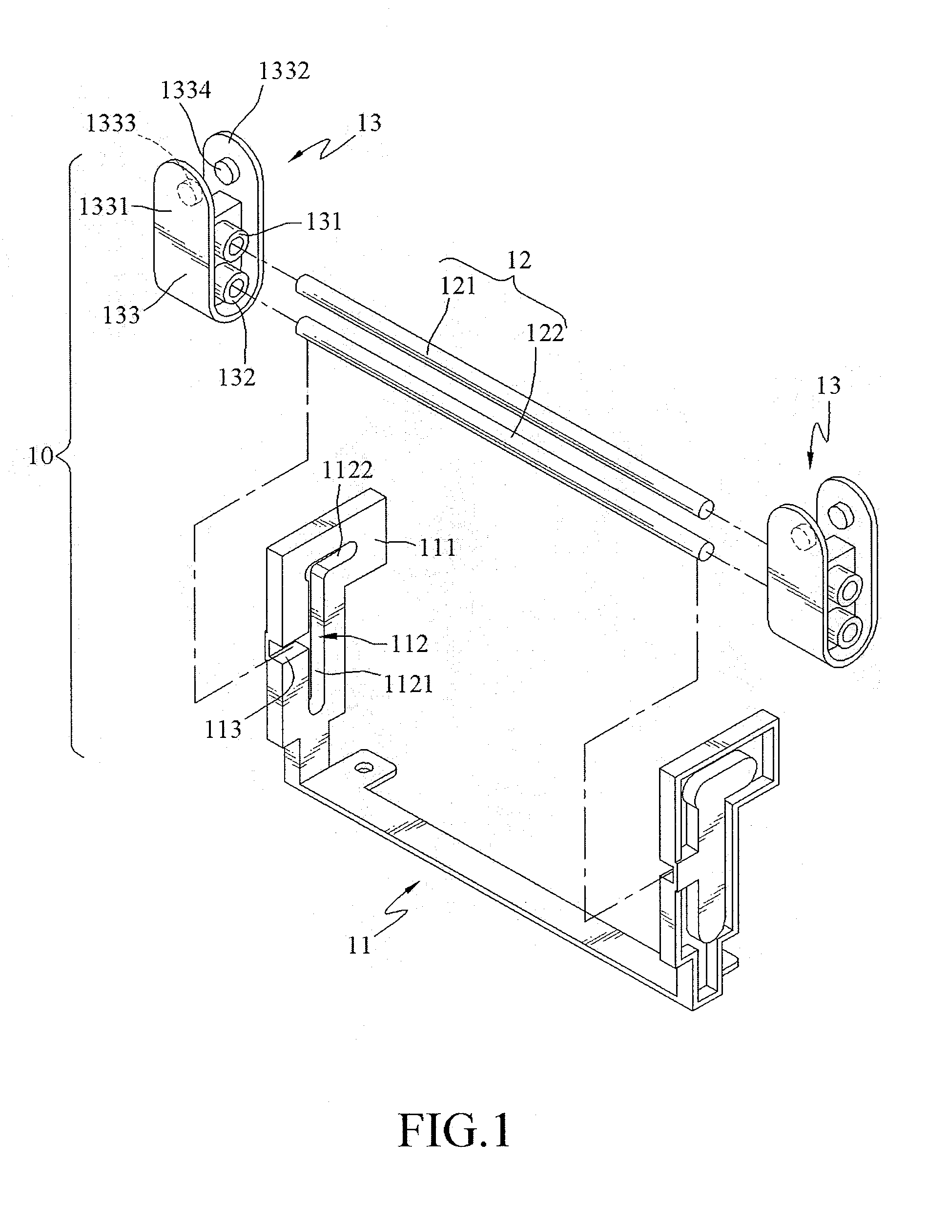
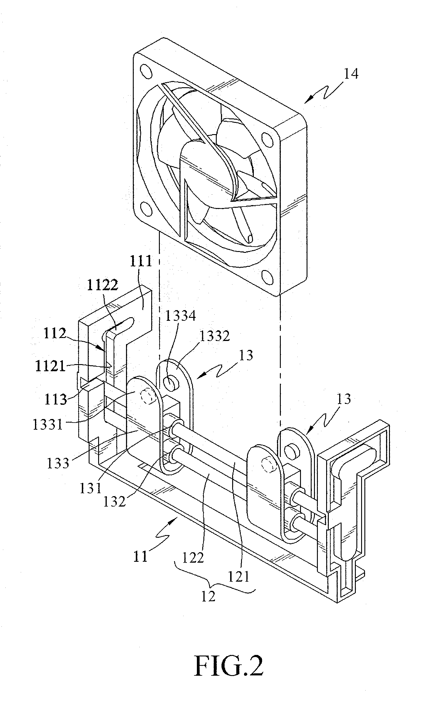
[0023] As shown in FIGS. 1 and 2, the heat dissipation device 10 provided by the present invention comprises a base frame 11, a moving frame 12, more than one retaining covers 13, and a heat dissipation fan 14. The base frame 11 substantially assumes a U shape and has two wing plates 111 spaced a distance from each other. A guide slot 112 substantially assuming an inverted L-shape are opened in the wing plates 111 and a vertical section 1121 and a horizontal section 1122 are defined. An entrance 113 is formed at a suitable position of the guide slot 112 for getting into the guide slot 112. The moving frame 12 comprises two shafts 121 and 122. The length of two shafts 121 and 122 is approximately equal to the pitch between the two wing plates 111, such that the two shafts 121 and 122 can enter the guide slot 112 through the entrance 113 and move within the range of the guide slot 112. The retaining cover 13 comprises two sliding sleeves 131 and 132 and a jacket 13...

second embodiment

The Second Embodiment

[0028] As shown in FIG. 5, according to a second embodiment of the present invention, a heat dissipation device 10a comprises a base frame 11a, a moving frame 12a, a retaining cover 13a, and a heat dissipation fan 14a. The base frame 11a assumes a plate shape and erects at one side of the memory socket 21 on the motherboard 20. A guide slot 111a is opened on the base frame 11a. The moving frame 12a comprises a main board 121a and wing plates 1211a and 1212a disposed on both sides of the main board 121a. The wing plate 1211a has a plurality of positioning holes 1213a (the wing plate 1212a is the same as the wing plate 1211a). The retaining cover 13a substantially assumes a U shape and has a pair of pivoting ears 131a and 132a. The pitch between the pivoting ears 131a and 132a is slightly smaller than the pitch between the wing plates 1211a and 1212a. The pivoting ear 131a has a positioning bump 1311a (the pivoting ear 132a is the same as the pivoting ear 131a). F...


PUM


Abstract

A heat dissipation device for dissipating heat from a plug-in electronic component, such as a memory is provided. The heat dissipation device includes a base frame, a moving frame, and a retaining cover. The base frame is disposed at one side of the electronic component. The moving frame is movably mounted on the base frame. A heat dissipation fan is mounted on the retaining cover, and the retaining cover is also movably mounted on the moving frame. In this manner, the heat dissipation fan has at least a retraction position where the heat dissipation fan is not overlaid above the electronic components so as to plug or remove the electronic component, and a heat dissipation position where the heat dissipation fan dissipates heat from the corresponding electronic component. Furthermore, the heat dissipation position changes in accordance with actual heat dissipation requirements, thereby providing an optimal heat dissipation mode.

Description

CROSS-REFERENCE TO RELATED APPLICATIONS [0001] This non-provisional application claims priority under 35 U.S.C. §119(a) on Patent Application No(s). 094121289 filed in Taiwan, R.O.C. on Jun. 24, 2005, the entire contents of which are hereby incorporated by reference. BACKGROUND OF THE INVENTION [0002] 1. Field of Invention [0003] The present invention relates to a heat dissipation device for dissipating heat from a heat-generating source, such as an electronic component. More particularly, the present invention relates to a heat dissipation device for a plug-in electronic component, such as a memory. [0004] 2. Related Art [0005] Computer system has become a main auxiliary tool for human beings due to its capability of doing a large amount of works such as operation and data storage. Along with continuous progress of science and technology, the computer system has been greatly improved in the aspect of operational efficiency and memory capacity. The computer system is composed of man...

Claims


Application Information

Patent Timeline
Patent Type & Authority Applications(United States)
IPC IPC(8): H05K7/20
CPCG06F1/20H05K7/20172H05K7/20154
Inventor HSIAO, YI-LIANG
Owner MICRO-STAR INTERNATIONAL
Why Eureka
Try Eureka