Condenser microphone

a condenser microphone and microphone body technology, applied in the direction of transducer casings/cabinets/supports, transducer casings/cabinets/supports, amplifiers with semiconductor devices/discharge tubes, etc., can solve the problems of affecting the output voltage of the maximum output voltage, and affecting the performance of the microphon

Active Publication Date: 2006-12-28
AUDIO-TECHNICA
View PDF3 Cites 12 Cited by
  • Summary
  • Abstract
  • Description
  • Claims
  • Application Information

AI Technical Summary

Benefits of technology

[0021] Even if the phantom power supply voltage is switched to another, the current that flows through the constant current diode remains substantially constant and the voltage on the cathode side of the constant current diode changes in accordance with the switching of the phantom power supply voltages. Since the voltage on the cathode side of the constant current diode is divided by the resistors into a bias for the transistor in emitter-follower

Problems solved by technology

When it is necessary for a compact microphone such as a tiepin type microphone to incorporate an impedance converter in a microphone unit section, if an FET is a type that does not incorporate a bias part, a bias part needs to be externally attached to the FET and there arises a problem that the microphone unit section becomes bulky.
In order for a microphone to operate in the above-mentioned range of voltage, priority is given generally in designing a microphone so as to operate at a minimum voltage of 11 V. Because of this, a drawback is presented that the maximum output voltage is kept low.
On the other hand, if design is made

Method used


Image

  • Condenser microphone
  • Condenser microphone
  • Condenser microphone

Examples


Embodiment Construction

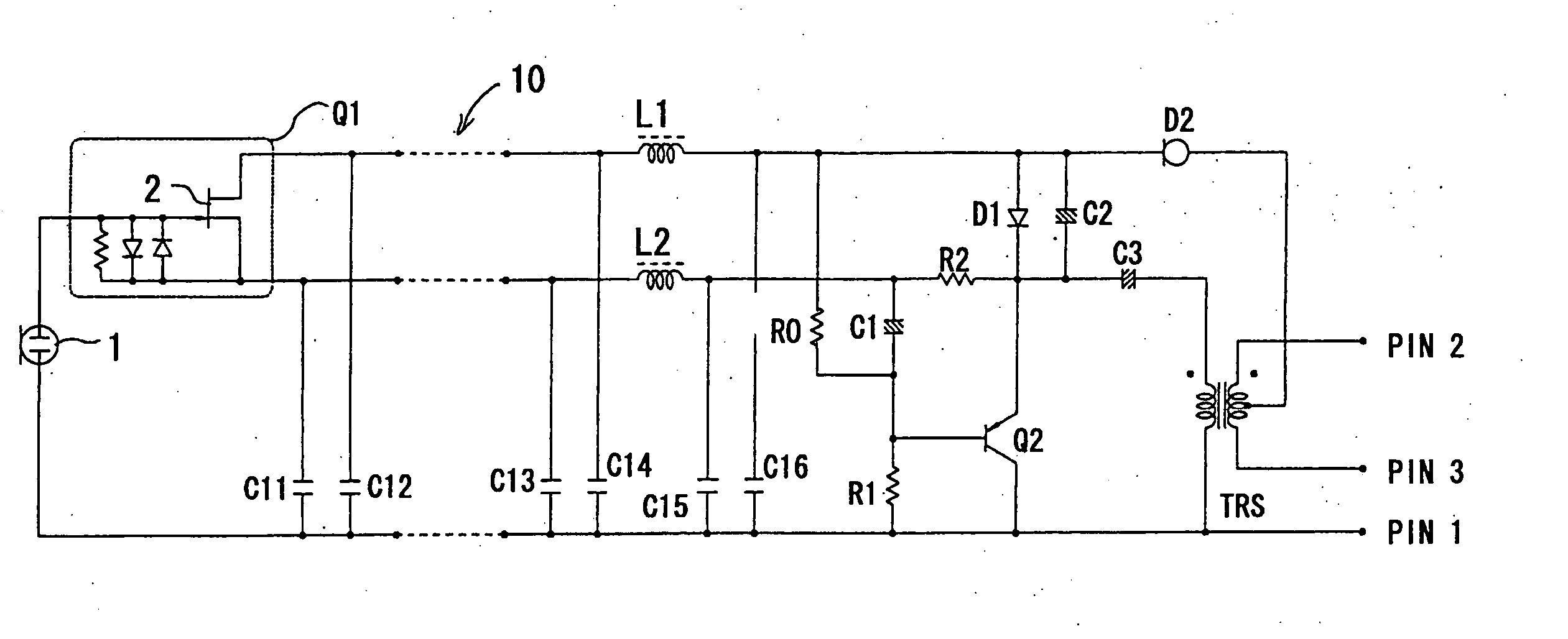
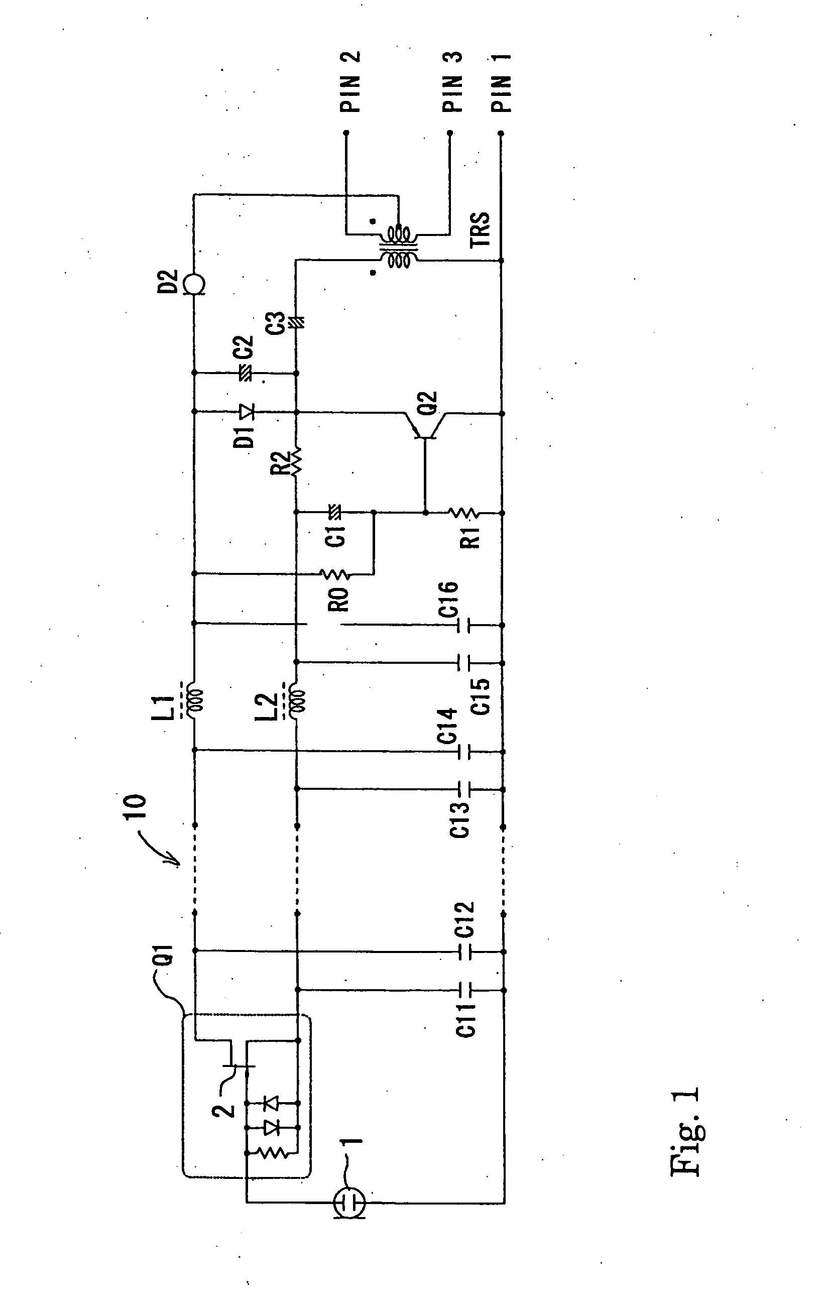
[0031] An embodiment of a condenser microphone according to the present invention is explained below with reference to FIG. 1 and FIG. 2.

[0032] In FIG. 1, symbol 1 denotes an electret condenser microphone unit, one end of the microphone unit 1 is connected to an input end of an impedance converter Q1, and the other end is connected to the ground. The impedance converter Q1 is constituted mainly by an FET 2. The impedance converter Q1 is a type that incorporates bias circuit elements such as a resistor and a diode. The anode and cathode of the FET 2 constitute balanced output end and immediately after the balanced output end, a transistor Q2 as a current amplifier circuit in emitter-follower connection is connected. In the example shown in FIG. 1, however, the configuration is such that a microphone head section consisting of the microphone unit 1 and the impedance converter Q1 and a power module section including the transistor Q2, an output transformer TRS, etc., are separated and...


PUM


Abstract

A condenser microphone is obtained, in which the bias of a current amplifier circuit in emitter-follower connection immediately after an impedance converter automatically changes in accordance with the switching of phantom power supply voltages and the maximum output level and the maximum permissible input sound pressure level are increased at any power supply voltage. The condenser microphone comprising a transistor Q2 in emitter-follower connection immediately after an FET 2 that constitutes an impedance converter Q1 has a constant current diode D2 connected to an output transformer TRS that also serves as a transformer for phantom power source supply and resistors R0 and R1 that divide the voltage on the cathode side of the constant current diode D2 into a bias voltage that causes the transistor Q2 to operate.

Description

BACKGROUND OF THE INVENTION [0001] 1. Field of the Invention [0002] The present invention is related to a condenser microphone that uses an impedance converter in which a bias diode and resistor are incorporated and, more particularly, is characterized by a current amplifier circuit connected immediately after the impedance converter. [0003] 2. Related Background of the Invention [0004] Since the output impedance of a microphone unit of a condenser microphone is high, impedance conversion is performed for output by an impedance converter configured mainly by a field effect transistor (hereinafter, referred to as an “FET”). In some cases, the FET constituting an impedance converter incorporates a bias diode and resistor and in other cases not. A circuit part such as a resistor and diode for applying a bias is indispensable for operating an FET. Therefore, that an FET does not incorporate a bias diode and resistor does not mean that a bias diode and resistor are integrally incorporate...

Claims


Application Information

Patent Timeline
IPC IPC(8): H04R3/00
CPCH04R3/00H04R19/04
Inventor AKINO, HIROSHI
Owner AUDIO-TECHNICA
Why Eureka
Try Eureka