Magnetic recording medium, magnetic recording and reproducing apparatus, and method for manufacturing magnetic recording medium

Inactive Publication Date: 2006-12-28
TDK CORPARATION
View PDF6 Cites 22 Cited by
  • Summary
  • Abstract
  • Description
  • Claims
  • Application Information

AI Technical Summary

Benefits of technology

[0023] Various exemplary embodiments of the present invention can achieve a magnetic recording medium which includes a recording layer formed in a concavo-convex pattern in which recording elements are formed as

Problems solved by technology

However, many problems including limitation of the magnetic head processing, erroneous recording of information on a track adjacent to a target track caused by broadening of a recording magnetic field of the magnetic head, crosstalk during reproduction, and the like are made apparent.
Thus, the improvement of the areal density by the conventional development approaches has reached the limit.
However, when the surface of the magnetic recording medium is excessively flat, stiction of the magnetic head to the surface of the magnetic recording medium can easily occur and therefore crash of the magnetic recording medium with the magnetic head can easily occur.
Thus, that distortion with the undulation leads to a variation in a magnetic gap.
However, when the magnetic gap

Method used


Image

  • Magnetic recording medium, magnetic recording and reproducing apparatus, and method for manufacturing magnetic recording medium
  • Magnetic recording medium, magnetic recording and reproducing apparatus, and method for manufacturing magnetic recording medium
  • Magnetic recording medium, magnetic recording and reproducing apparatus, and method for manufacturing magnetic recording medium

Examples


working example 1

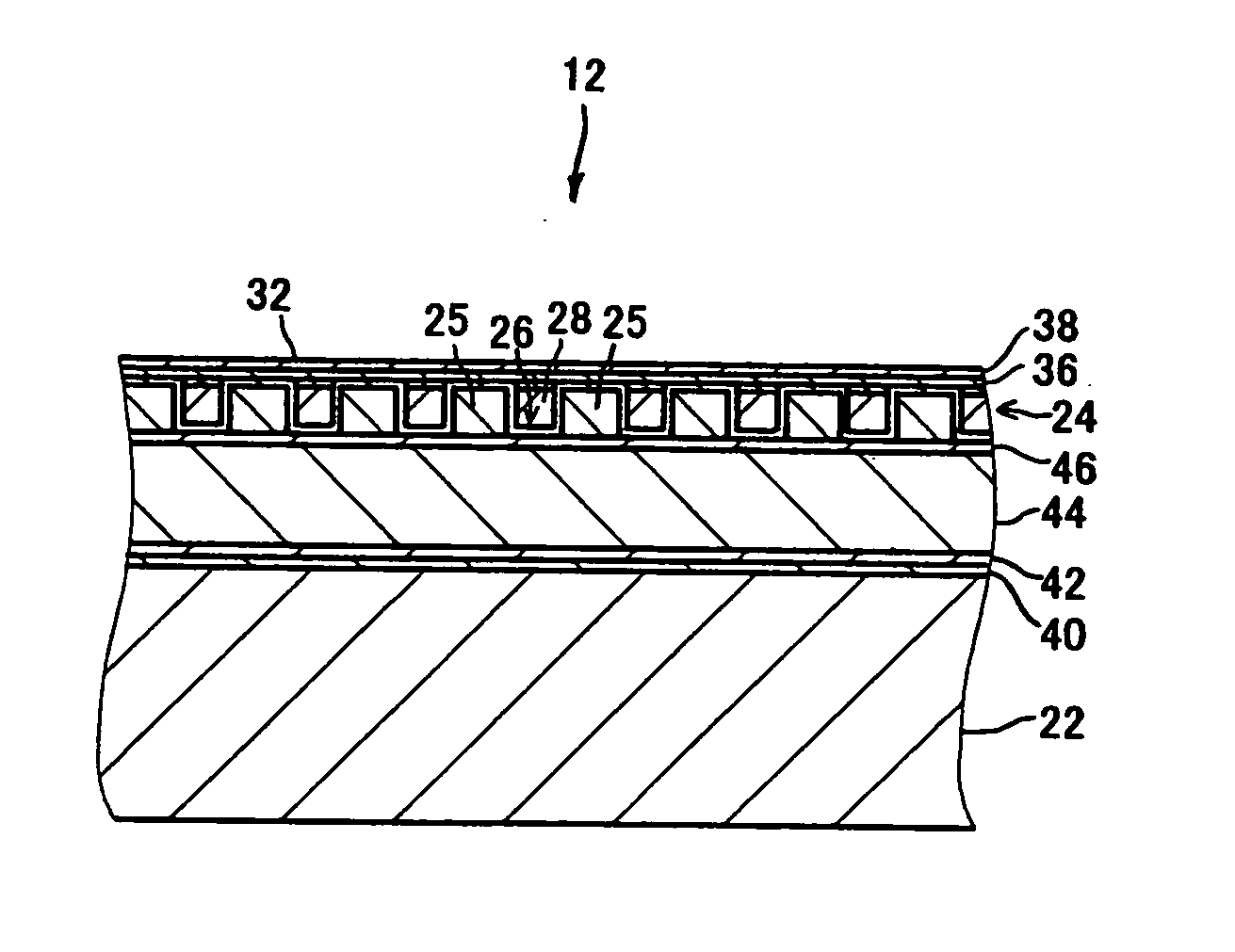
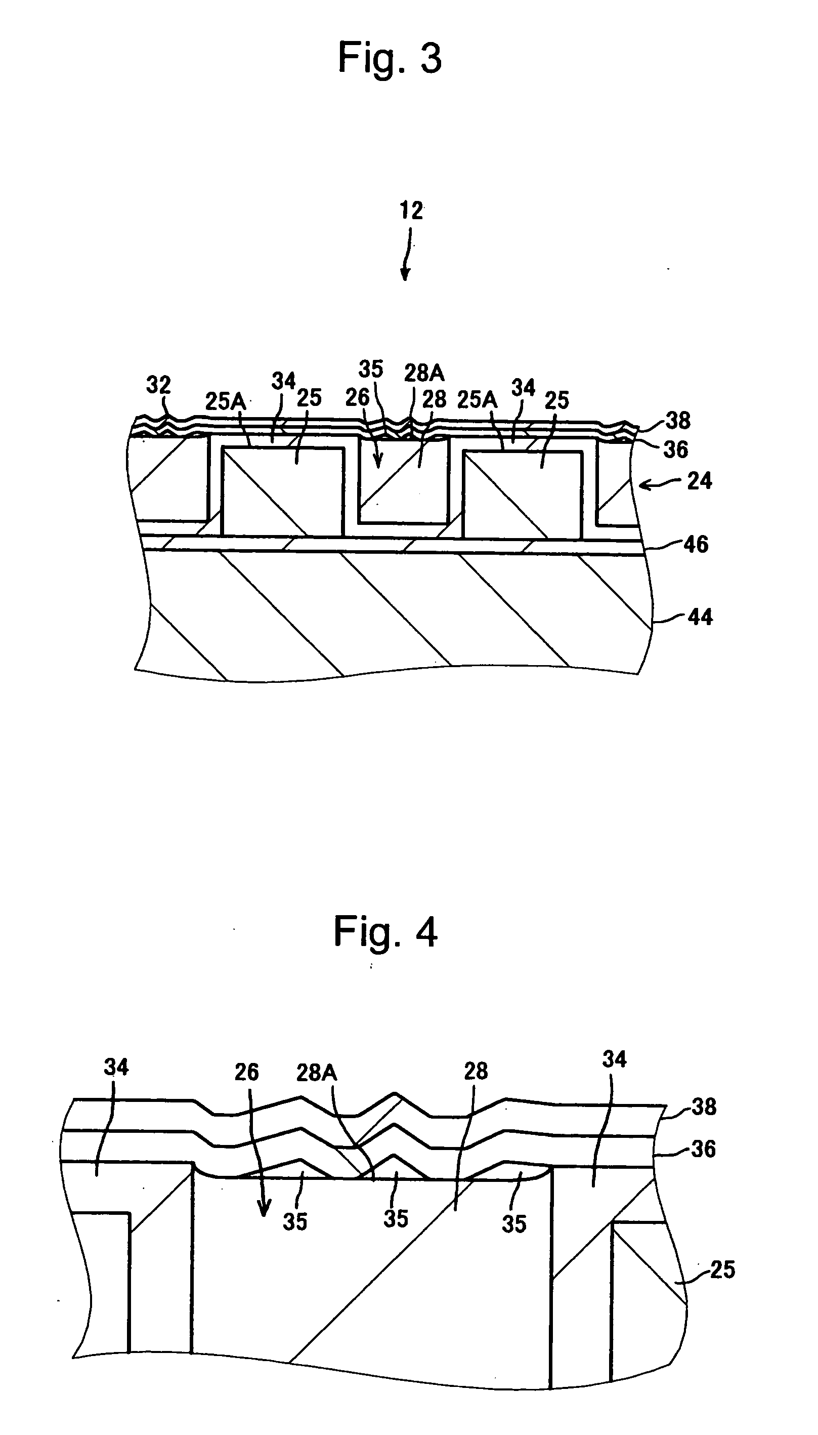
[0092] Ten magnetic recording media 12 having the same structure as that described in the above first exemplary embodiment (see FIGS. 2 to 4) were manufactured. The main structure of the manufactured magnetic recording media 12 is now described.

[0093] The substrate 22 had a diameter of approximately 65 mm and was made of glass. The recording layer 24 had a thickness of approximately 20 nm and was made of a CoCrPt alloy. The filling material 28 was SiO2. The stop film 34 had a thickness of approximately 3 nm and was made of Ta. The protective layer 36 had a thickness of approximately 2 nm and was made of DLC. The lubricating layer 38 had a thickness of approximately 1 nm and was made of PFPE. A track pitch (a pitch in a track-width direction between the recording elements 25) in the data area was approximately 200 nm and a width of the top surface of each recording element 25 (a track width) was approximately 100 nm.

[0094] In the stop film deposition step (S110), as a sputtering co...

working example 2

[0102] Ten magnetic recording media 12 having the same structure as that described in the above third exemplary embodiment (see FIG. 11) were manufactured. More specifically, unlike Working Example 1, the filling material 28 was deposited to have a thickness of 21 nm, that was thicker than the depth of the concave portion 26, 20 nm, by 1 nm, in the filling material deposition step (S112). That is, the filling material 28 was deposited in such a manner that the top surface of the filling material 28 in the concave portions 26 was higher than the top surface of the stop film 34 on the recording elements 25 by 1 nm.

[0103] As the coating member 35, Mo was deposited to have a thickness of 3 nm in the coating member deposition step (S114), as in Working Example 1.

[0104] The coating member 35 was completely removed in the flattening step (S116). Except for the above, Working Example 2 was the same as Working Example 1.

[0105] For each of those magnetic recording media 12, the arithmetica...

working example 3

[0107] Unlike Working Example 1, a step having a height of approximately 2.5 nm was provided between the portion of the surface 32 above the filling material 28 and the portion above the recording element 25. More specifically, the filling material 28 was deposited to have a thickness of 17 nm that was thinner than the depth of the concave portion 26, 20 nm, by 3 nm in the filling material deposition step (S112). That is, the filling material 28 was deposited in such a manner that the top surface of the filling material 28 in the concave portions 26 was lower than the top surface of the stop film 34 on the recording elements 25 by 3 nm.

[0108] Moreover, in the flattening step (S116), etching was stopped when the coating member 35 was partially removed and the step between the top surface of the coating member 35 and the filling material 28 that was not coated with the coating member 35 and the top surface of the stop film 34 on the recording element 25 reached approximately 2.5 nm. ...


PUM


Abstract

A magnetic recording medium that includes a recording layer formed in a predetermined concavo-convex pattern in which recording elements are formed as convex portions, has high areal density, cannot cause crash of a magnetic head easily, and has high reliability, and a magnetic recording and reproducing apparatus including that magnetic recording medium are provided. The magnetic recording medium includes: the recording elements formed as the convex portions of the recording layer formed in a predetermined concavo-convex pattern over a substrate; and a filling material with which a concave portion between the recording elements is filled. The surface roughness of a portion of a surface of the medium above the filling material is larger than that of portions of the surface above the recording elements.

Description

BACKGROUND OF THE INVENTION [0001] 1. Field of the Invention [0002] The present invention relates to a magnetic recording medium including a recording layer formed in a predetermined concavo-convex pattern in which recording elements are formed as convex portions, a magnetic recording and reproducing apparatus including that magnetic recording medium, and a method for manufacturing the magnetic recording medium. [0003] 2. Description of the Related Art [0004] Conventionally, for a magnetic recording medium such as a hard disk, various types of development such as miniaturization of magnetic particles forming a recording layer, a change in a material for the magnetic particles, and miniaturization of heading have been made to largely improve areal density of the recording layer. The improvement of the areal density is expected to continue. However, many problems including limitation of the magnetic head processing, erroneous recording of information on a track adjacent to a target tr...

Claims


Application Information

Patent Timeline
IPC IPC(8): G11B5/64G11B5/65
CPCG11B5/855
Inventor SUWA, TAKAHIROHATTORI, KAZUHIROOKAWA, SHUICHI
Owner TDK CORPARATION
Why Eureka
Try Eureka