Electrosurgical instrument and method of use

a technology of electrosurgical instruments and jaws, applied in the field of electrosurgical jaw structures, can solve the problems of non-uniform denatured tissue not creating a seal with significant strength, and achieve the effects of limiting electrosurgical energy delivery, preventing arcs and tissue charring, and high energy

Inactive Publication Date: 2006-12-28
SURGRX
View PDF4 Cites 250 Cited by
  • Summary
  • Abstract
  • Description
  • Claims
  • Application Information

AI Technical Summary

Benefits of technology

[0014] Various embodiments of the invention provide an electrosurgical jaw structure comprising first and second opposing jaws wherein at least one jaw carries a pressure sensitive variable resistance material that deforms slightly under tissue-engaging pressure and can be transformed from an insulative layer to a conductive electrode layer under a selected pressure level. The pressure sensitive surface will thus adjust Rf current flow therethrough in response to local tissue-engaging pressure. The pressure sensitive variable resistance material thus can deliver high amount of energy to more highly compressed tissue, and limit electrosurgical energy delivery into desiccated tissue regions that shrink to prevent arcs and tissue charring.

Problems solved by technology

However, such non-uniformly denatured tissue will not create a seal with significant strength, for example in 2 mm. to 10 mm. arteries that contain high pressures.
Such surface coagulation does not create a weld that provides any substantial strength in the affected tissue.

Method used


Image

  • Electrosurgical instrument and method of use
  • Electrosurgical instrument and method of use
  • Electrosurgical instrument and method of use

Examples


Embodiment Construction

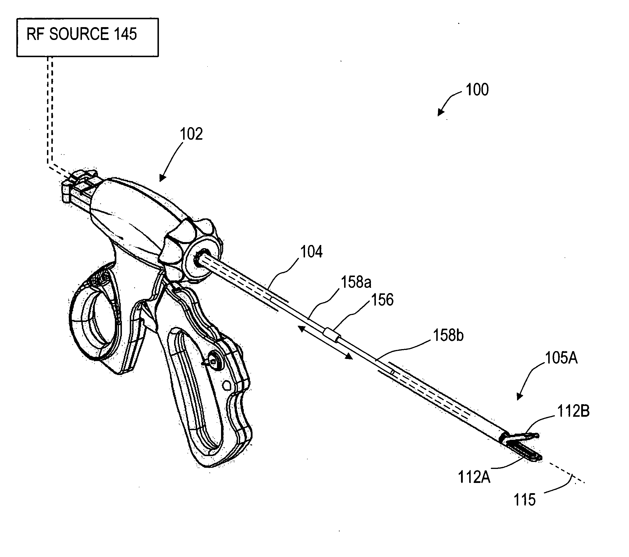
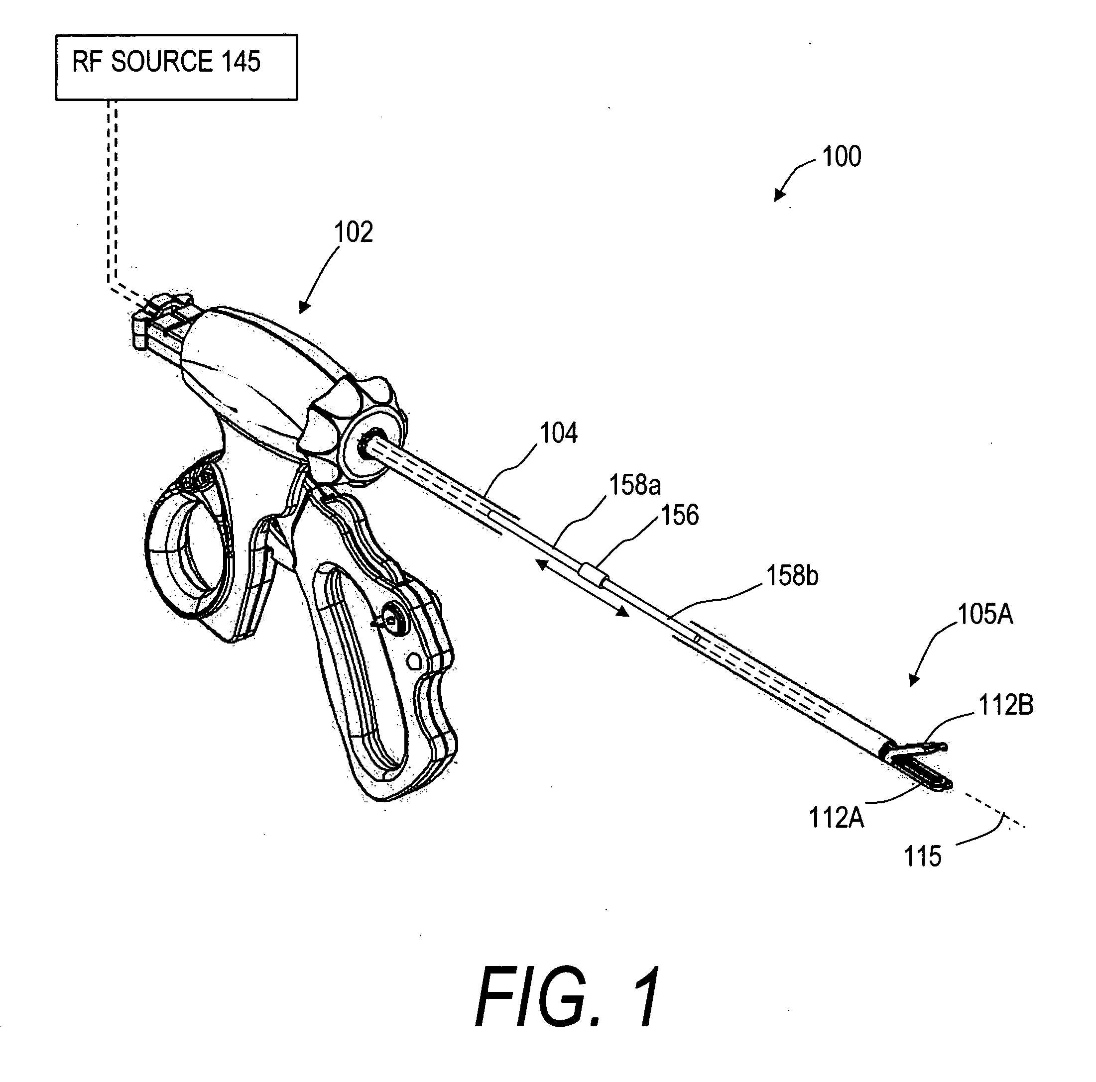
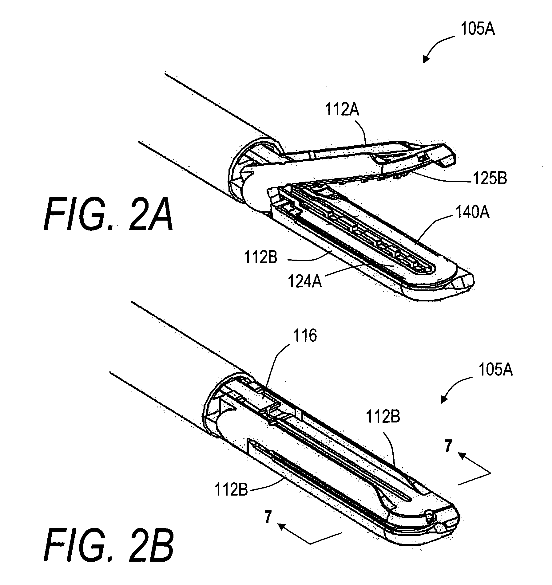
[0027]FIG. 1 illustrates an exemplary instrument 100A having handle 102 that is coupled to introducer member 104 that carries a working end comprising an electrosurgical jaw structure 105A corresponding to the invention. The jaw structure includes first (lower) jaw element 112A and second (upper) jaw element 112B that close or approximate about axis 115. The tissue-engaging surfaces 124A and 124B of jaws 112A and 112B carry electrosurgical functionality for sealing or welding tissue. In one embodiment as in FIGS. 2A-2B and 3, at least one jaw carries (the upper jaw) carries a surface layer 125B of a pressure sensitive variable resistive material for controlling bi-polar Rf energy delivery to engaged tissue. Any electrosurgical jaw structure can carry such pressure sensitive surfaces, which includes endoscopic and open surgery instruments with any curved or straight jaw shapes. The jaws can be opened and closed by any suitable mechanism. In one embodiment shown in FIGS. 1-3, the jaws...


PUM


Abstract

Electrosurgical jaw structures are disclosed that include pressure sensitive variable resistive materials in electrosurgical energy delivery surfaces for welding tissue. The pressure sensitive materials are configured to have megaohm impedance when not engaging tissue and can transform into highly conductive electrodes when compressed under a selected pressure. In a method of the invention, the pressure sensitive variable resistive materials prevent arcing and tissue desiccation when applying bi-polar Rf current to tissue engaged under high compression in an electrosurgical jaw structure.

Description

CROSS-REFERENCE TO RELATED APPLICATIONS [0001] This application claims benefit of U.S. Provisional Patent Application Ser. No. 60 / 598,713 filed Aug. 3, 2004 titled Surface-Conforming Electrosurgical Electrode; and this application is a continuation-in-part of U.S. patent application Ser. No. 10 / 032,867 filed Oct. 22, 2001 titled Electrosurgical Jaw Structure for Controlled Energy Delivery, and this application is also a continuation-in-part of Ser. No. 10 / 351,449 filed Jan. 22, 2003 titled Electrosurgical Instrument and Method of Use; all of the above applications are incorporated herein and made a part of this specification by this reference.BACKGROUND OF THE INVENTION [0002] Field of the Invention [0003] Embodiments of the invention relate to medical devices and methods and more particularly relates to an electrosurgical jaw structure and methods for creating high strength welds in tissue. [0004] In the prior art, various energy sources such as radiofrequency (Rf) sources, ultraso...

Claims


Application Information

Patent Timeline
Patent Type & Authority Applications(United States)
IPC IPC(8): A61B18/14
CPCA61B18/1442A61B2019/464A61B2018/1495A61B2090/064
Inventor SHADDUCK, JOHN H.TRUCKAI, CSABA
Owner SURGRX
Why Eureka
Try Eureka