Cap and activation tool

a technology of activation tool and prosthetic implant, which is applied in the field of prosthetic implants, can solve the problems of affecting the safety of patients, the inability of the tool to generally grip the wall, the damage of the insertion tool, the metal shell or both, and the cost implications of hospitals, so as to reduce the tendency to distort the sector, improve the control provided over the foot, and increase the ease of connection and removal.

Active Publication Date: 2006-12-28
FINSBURY DEV
View PDF49 Cites 16 Cited by
  • Summary
  • Abstract
  • Description
  • Claims
  • Application Information

AI Technical Summary

Benefits of technology

[0046] Any suitable tool arrangement of fixed component and movable component may be used. The fixed component may be directly attached to the arm of the tool and the movable component may be attached via a rod to a hinged means on the arm. The rod connecting the movable component to the handle may include articulating means. A portion of the articulation means may provide a second point of contact between the rod and the handle. The articulation means enables the movement of the movable portion of the foot to be generally horizontal, i.e. in the plane of the foot rather than arcuate. This horizontal movement improves the control provided over the foot increasing the ease with which it can be connected to and removed from engagement with the cap. In one arrangement, the tool is configured such that its movement in use decreases any tendency to distort the sectors out of the plane of the cap.

Problems solved by technology

Further, as the wall thickness of the shell is generally kept to a minimum, the tool cannot generally grip the wall.
As a result it is often not strong enough for the impaction forces applied which may result in damage to the insertion tool, the metal shell or both.
Having to purchase a range of such tools has cost implications for hospitals.
With this type of cup the inner hemisphere is not a convenient place to locate a mechanical feature on which the insertion tool could grip.
First, the presence of any mechanical feature on the inner surface would reduce the surface area of the prosthetic articulation.
Secondly, it could cause damage to the highly polished surface of the metal.
A further problem which may be encountered is that the forces exerted through the insertion tool during impaction, repositioning and / or extraction may cause the wall of the acetabular cup to be distorted.
This is particularly a problem when the cup being inserted, repositioned and / or extracted, is a resurfacing cup since these generally have a thinner wall thickness than standard acetabular cups.
Whilst this arrangement may offer certain advantages over prior art systems, it is apparent that the system is only suitable for use with a cup having a significant surface area on the annular face.

Method used


Image

  • Cap and activation tool
  • Cap and activation tool
  • Cap and activation tool

Examples


Embodiment Construction

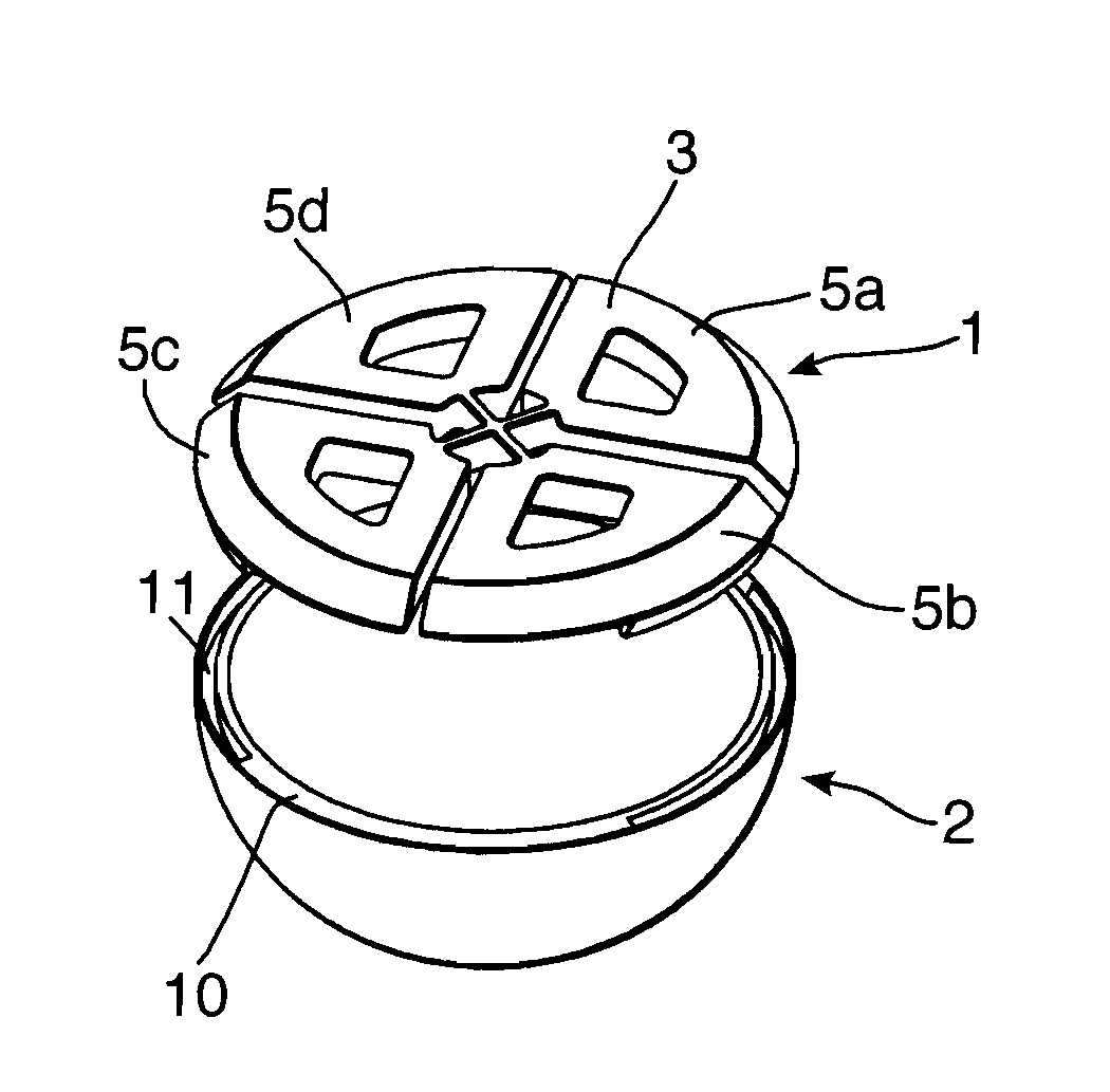
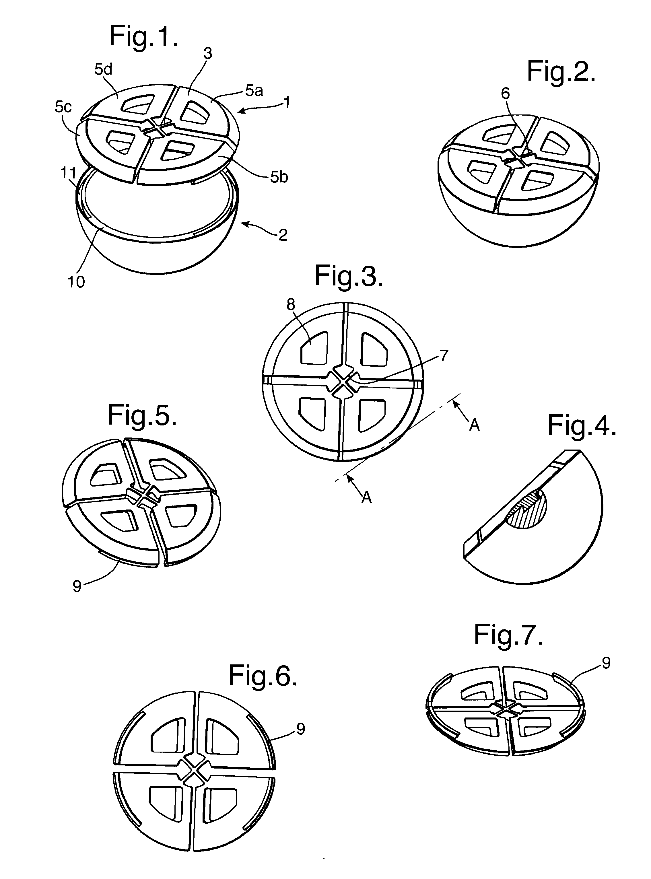
[0082] As illustrated in FIGS. 1 to 7, a cap 1 is provided for an acetabular cup prosthesis 2. The cap comprises an impaction plate 3 comprising four sectors 5a, 5b, 5c and 5d. Each sector is connected to a connection point 6 via flanges 7.

[0083] Each sector includes an aperture 8 which provides means for connecting the cap to an insertion tool.

[0084] As illustrated most clearly in FIG. 6, the gaps between the sectors are not equal.

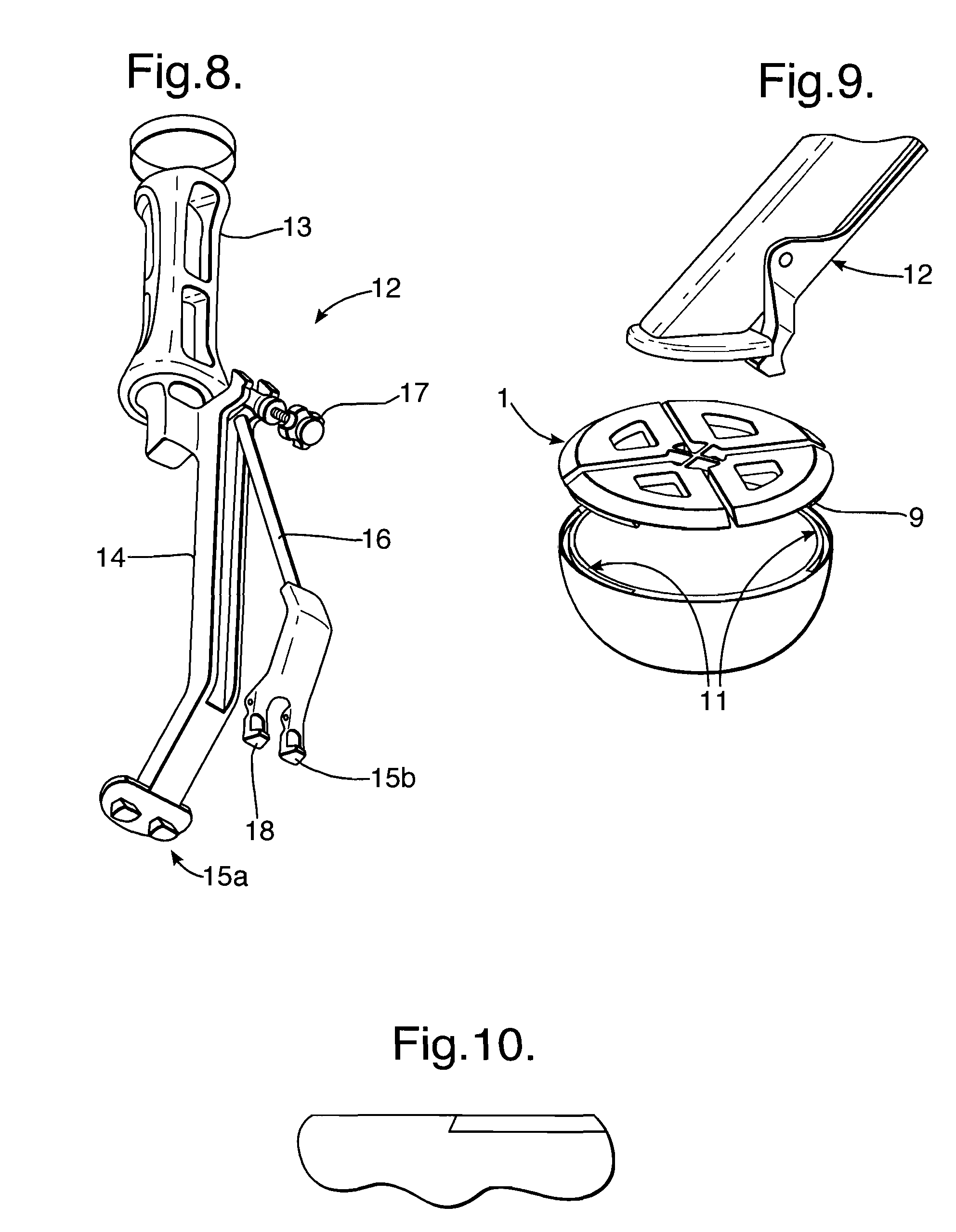
[0085] Lugs in the form of ribs 9 extend from each of the sectors. As illustrated in FIG. 7 the ribs are angled inwardly. These ribs are shaped to interact with dovetailed edges to corresponding grooves 11 in the rim 10 of the cup 2. The dovetailed edge is illustrated in FIGS. 4 and 10.

[0086] One arrangement of a tool 12 is illustrated in FIG. 8. The tool 12 comprises a handle 13, an arm 14 and a foot 15a and 15b. The foot comprises a fixed component 15a and a movable component 15b. The movable foot component 15b is connected to the arm 14 by means of...


PUM


Abstract

A cap used during the insertion of an acetabular cup prosthesis. The cap comprises an impaction plate having an upperside and an underside. The impaction plate comprises a plurality of separate sectors mutually connected at a connection point on the impaction plate by means of flanges. Each sector includes interlocking means which in use enable the impaction plate to be connected to an introduction tool. The cap also comprises at least one lug extending downwardly from the underside of each sector. The lug is located at the portion of the underside of the impaction plate which will in use enable the lug to be interconnected with a corresponding recess on an internal wall, an external wall or a rim of a prosthesis.

Description

CROSS-REFERENCE TO RELATED APPLICATIONS [0001] This application claims priority to foreign applications UK Pat. App. No. 0509766.2 filed May 12, 2005, and UK Pat. App. No. 0519865.0 filed Sep. 29, 2005, both of which are hereby incorporated by reference. BACKGROUND OF THE INVENTION [0002] The present invention relates to a cap for a prosthetic implant particularly a prosthetic acetabulum implant and to an introduction tool for use therewith. [0003] The replacement of all or a part of the bone surface of an articulation with a prosthetic implant has become a common surgical procedure. The procedure requires the surgeon to exercise both precision and delicacy in the placement of the prosthetic implant. However, it is frequently necessary for the surgeon also to exercise a degree of force, sometimes a vigorous force, in order to situate the prosthetic implant in the desired location on the bone surface. [0004] For example, in an operation to insert a prosthetic acetabulum in a patient'...

Claims


Application Information

Patent Timeline
Patent Type & Authority Applications(United States)
IPC IPC(8): A61F2/00
CPCA61F2/0095A61F2/34A61F2/4609A61F2002/30225A61F2002/30382A61F2002/30484A61F2230/0069A61F2002/30825A61F2002/4623A61F2002/4681A61F2220/0025A61F2220/0033A61F2002/30718A61F2/4603A61F2002/30331
Inventor WOZENCROFT, ROBERT MICHAELTUKE, MICHAEL ANTHONYHAWSON, NICHOLAS LEE
Owner FINSBURY DEV
Why Eureka
Try Eureka