
Method and apparatus for communicating transactions between an industrial controller and a programming interface

a technology of industrial controllers and programming interfaces, applied in the field of industrial control systems, can solve problems such as costly downtime or product defects, interrupting the series of commands midstream, and affecting the operation of the series,

Active Publication Date: 2006-12-28
ROCKWELL AUTOMATION TECH
View PDF25 Cites 46 Cited by
  • Summary
  • Abstract
  • Description
  • Claims
  • Application Information

AI Technical Summary

Benefits of technology

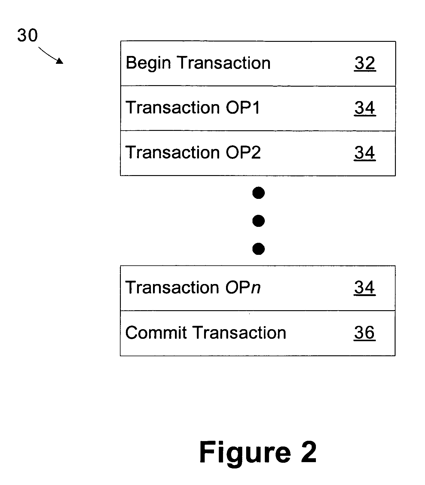
[0012] The present inventors have recognized that a transaction process may be employed by the programming interface that communicates with an industrial controller. The transaction includes a plurality of operations followed by a commit transaction command. The industrial controller preprocesses the operations, but desi...

Problems solved by technology

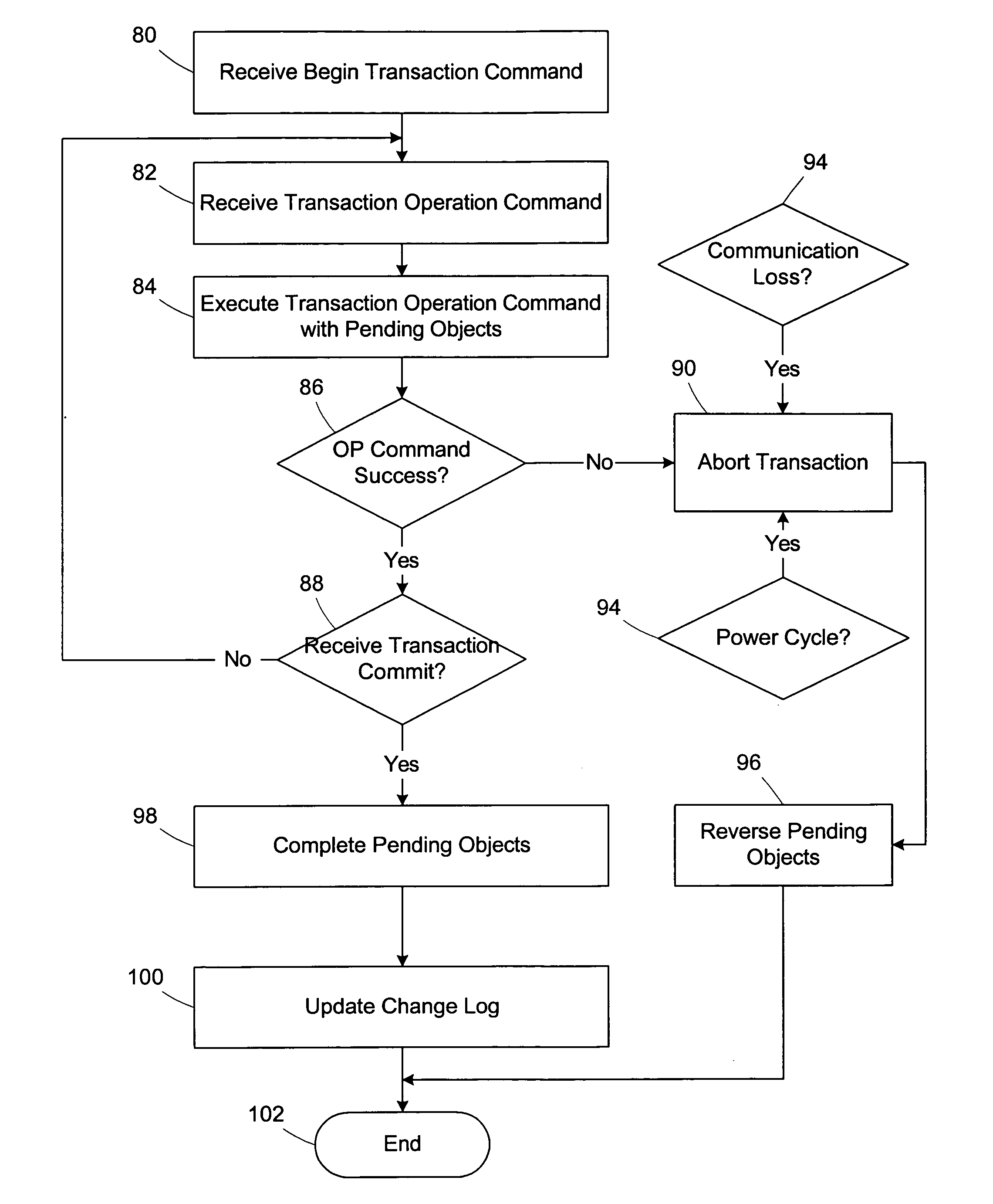
The nature of the process may be such that interrupting the process to reprogram the controller would cause costly downtime or product defects.
In some cases, a power cycling event or the loss of the communication link between the workstation and the controller may disrupt the series of commands midstream.
The series may also be disrupted if the controller cannot process one of the commands, for example due to the state of an object being modified or a lack of memory space for an object being added.
In cases where the series of commands is interrupted or fails, it is difficult to clean up the partially completed process for instantiating the added module or program change.
It may not be feasible to shut down the process to allow the last known good image to be reloaded onto the controller.
Hence, the clean up may need to be performed manually, which is time-consuming, potentially expensive, and imprecise.
For example, all of the objects created in the controller may not be properly removed during the clean up process.
These artifacts may lead to wasted storage space or even system instability.

Method used


Image

  • Method and apparatus for communicating transactions between an industrial controller and a programming interface
  • Method and apparatus for communicating transactions between an industrial controller and a programming interface
  • Method and apparatus for communicating transactions between an industrial controller and a programming interface

Examples


Embodiment Construction

[0026] One or more specific embodiments of the present invention will be described below. It is specifically intended that the present invention not be limited to the embodiments and illustrations contained herein, but include modified forms of those embodiments including portions of the embodiments and combinations of elements of different embodiments as come within the scope of the following claims. It should be appreciated that in the development of any such actual implementation, as in any engineering or design project, numerous implementation-specific decisions must be made to achieve the developers' specific goals, such as compliance with system-related and business related constraints, which may vary from one implementation to another. Moreover, it should be appreciated that such a development effort might be complex and time consuming, but would nevertheless be a routine undertaking of design, fabrication, and manufacture for those of ordinary skill having the benefit of thi...


PUM


Abstract

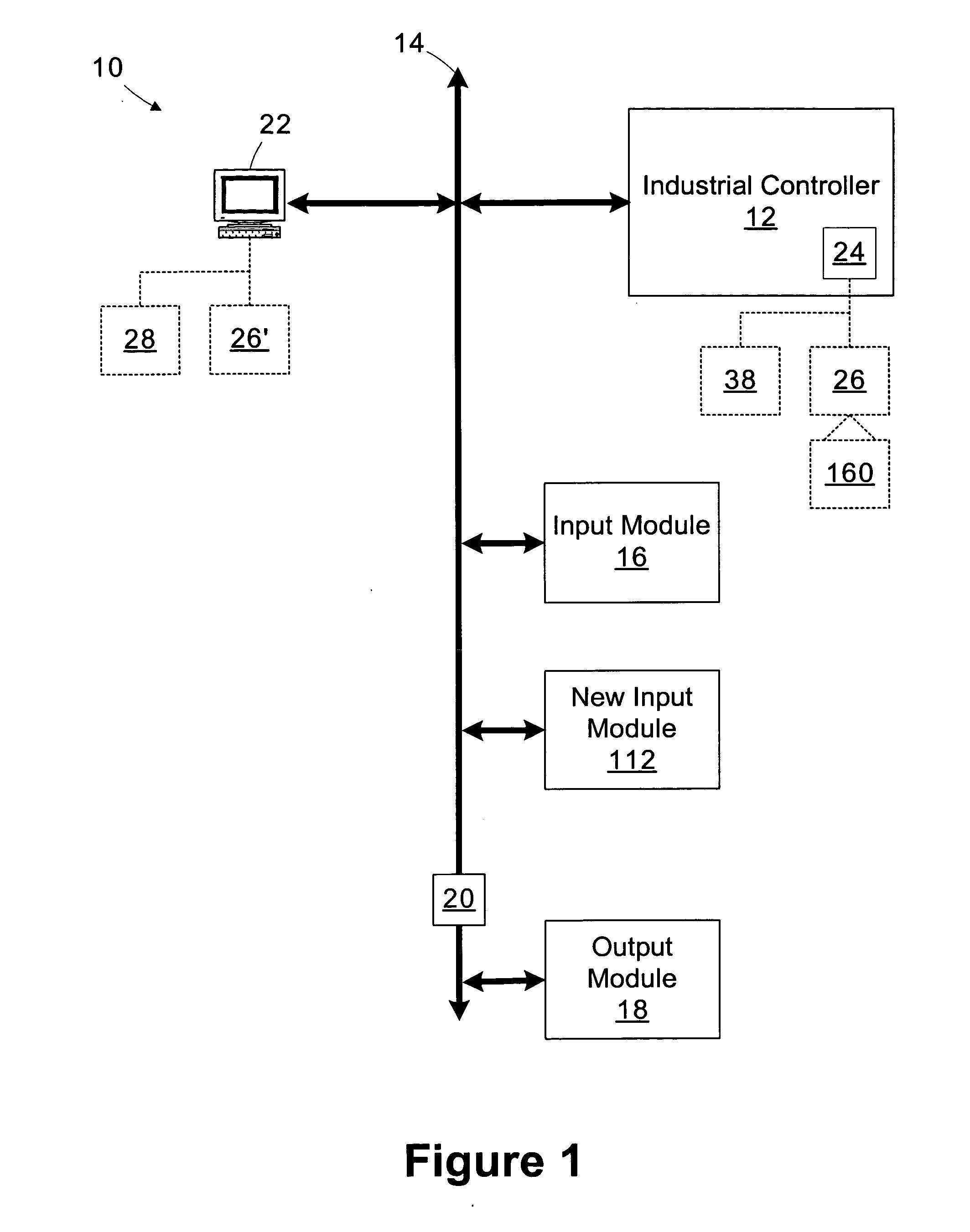
An industrial control system includes an industrial controller and a programming interface. The industrial controller maintains a control program for interfacing with a controlled process. The programming interface is operable to communicate a transaction to the industrial controller. The transaction includes a plurality of operations for modifying the control program followed by a commit transaction command. The industrial controller is operable to preprocess the plurality of operations, designate the plurality of operations with a pending status, and commit the operations and clear the pending status responsive to receiving the commit transaction command.

Description

CROSS-REFERENCE TO RELATED APPLICATIONS [0001] Not applicable. STATEMENT REGARDING FEDERALLY SPONSORED RESEARCH OR DEVELOPMENT [0002] Not applicable BACKGROUND OF THE INVENTION [0003] The present invention relates to industrial control systems and, in particular, to a method and apparatus for communicating transactions between an industrial controller and a programming interface. [0004] This section of this document is intended to introduce various aspects of art that may be related to various aspects of the present invention described and / or claimed below. This section provides background information to facilitate a better understanding of the various aspects of the present invention. It should be understood that the statements in this section of this document are to be read in this light, and not as admissions of prior art. [0005] Industrial controllers are special purpose computers used for controlling industrial processes or manufacturing equipment. Under the direction of a stor...

Claims


Application Information

Patent Timeline
IPC IPC(8): G06F17/30
CPCG05B19/0426G05B2219/23255G05B2219/23302G05B2219/23335G05B2219/24139Y10S707/955G06F11/1474G06F11/2038G06F9/3004G06F9/30087G06F9/466Y02P90/02
Inventor JOHNSTON, DAVID A.BAKER, JACOB S.CAPRILES, LUIS A.HUSTED, RAYMOND R.PIERCE, SCOTT A.REID, DOUGLAS W.SEPSI, ROBERT R.SUMERAUER, DOUGLAS B.
Owner ROCKWELL AUTOMATION TECH
Learn More