Network system based on policy rule

Inactive Publication Date: 2006-12-28
FUJITSU LTD
View PDF1 Cites 173 Cited by
  • Summary
  • Abstract
  • Description
  • Claims
  • Application Information

AI Technical Summary

Benefits of technology

[0016] It is an object of the present invention to provide a technique and a method capable

Problems solved by technology

Such an increase in traffic has been accompanied by an increase in processing load on a network device which constitutes the network, causing transfer delay or discard of a packet through the network with the result of deterioration of service quality (QoS: Quality of Service).
However, the following problems still remain even when the above-described conventional method is used.
According to currently-operated primitive policies, as the operation progres

Method used


Image

  • Network system based on policy rule
  • Network system based on policy rule
  • Network system based on policy rule

Examples


first operation example

[0112] According to the network system 1 based on the policy rule of a first operation example, a multi-policy rule is created by combining single policy rules of the same condition according to an operation purpose, with the result that the IP network 3 diversified and instantaneously changed in state can be flexibly controlled.

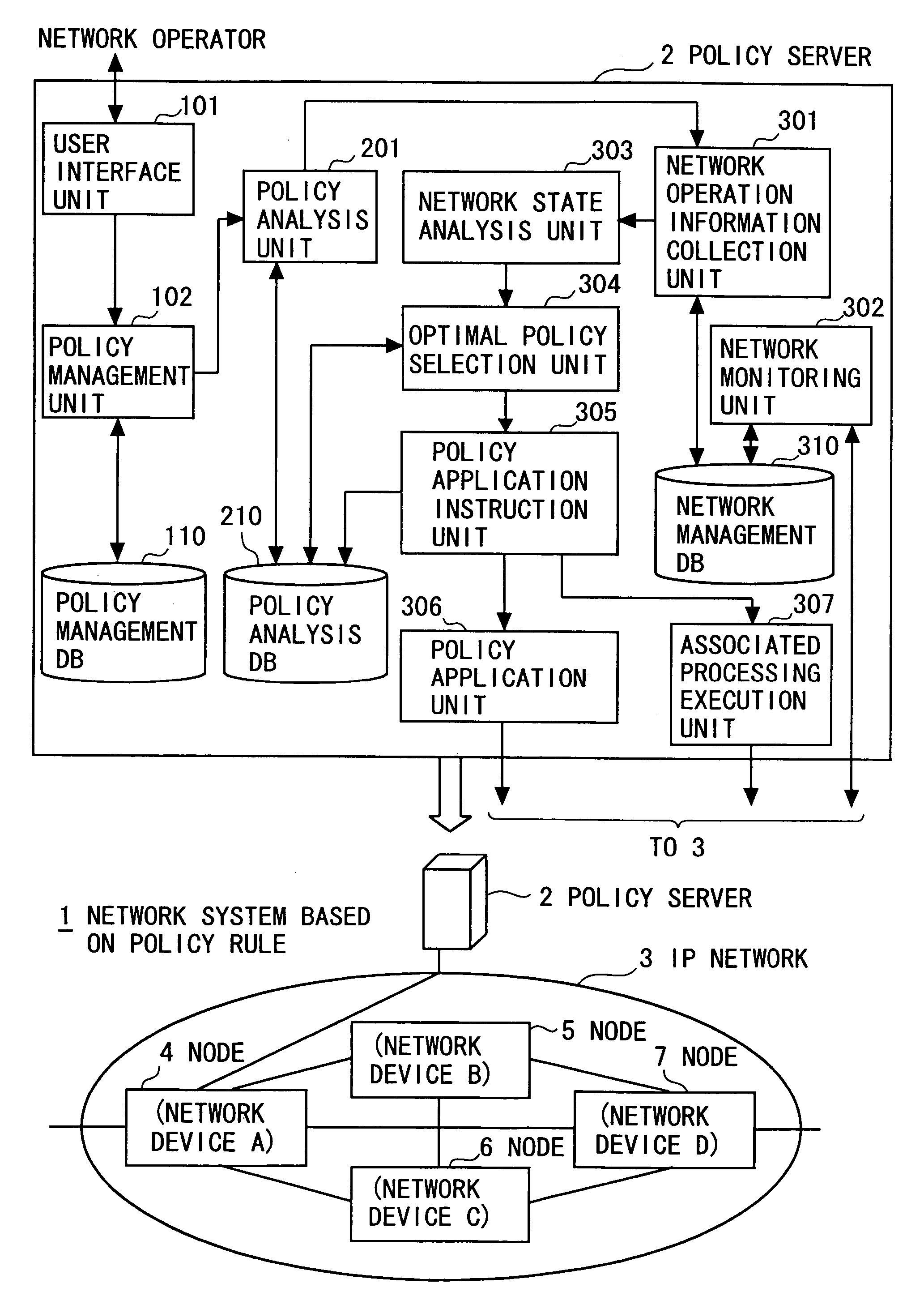
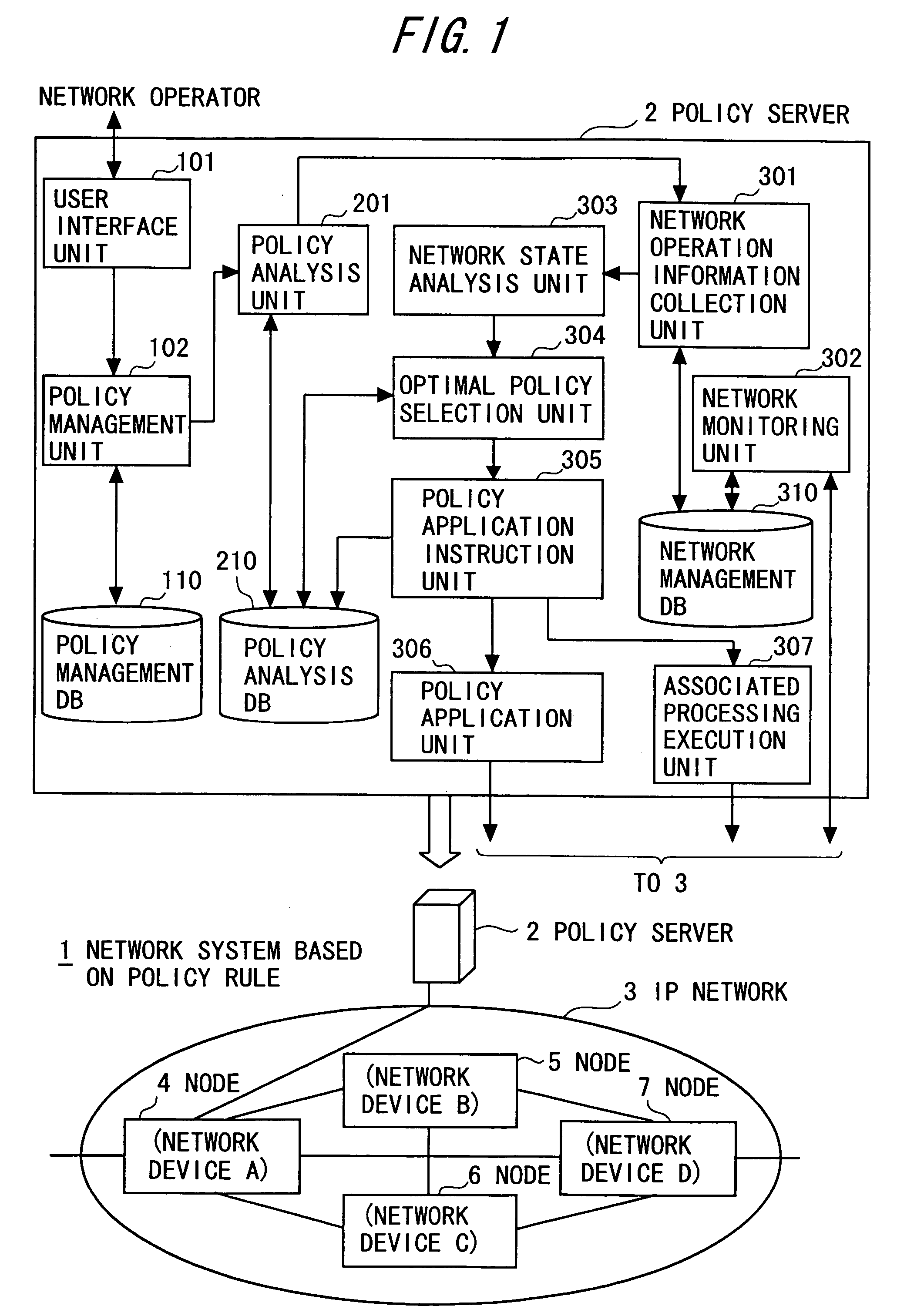
[0113] As shown in FIG. 3, the network operator utilizes the maintenance / operation terminal connected to the policy server 2 through the IP network 3 to designate “Policy Rule 1” and make a registration request of a policy rule through the user interface unit 101 (S10101 and S10102 shown in FIG. 6). “Policy Rule 1” includes “Condition 1” as a condition indicating occurrence of a line-basis trouble with regard to the traffic (IP flow) flowing from the user terminal X to the user terminal Y through the route 1 and “Action 1” as an action of path switching so that the traffic can flow from the user terminal X to the user terminal Y through the route 2.

[0114] ...

second operation example

[0136] According to the network system 1 based on the policy rule of a second operation example, an order of priority (priority) according to an operation purpose is given to single policy rules of the same condition and application is performed according to the order of priority, with the result that the IP network 3 diversified and instantaneously changed in state can be flexibly controlled.

[0137] As shown in FIG. 4, the network operator utilizes the maintenance / operation terminal connected to the policy server 2 to designate “Policy Rule 4” and make a registration request of a policy rule through the user interface unit 101 (S10101 and S10102 shown in FIG. 6). “Policy Rule 4” includes “Condition 4” as a condition indicating that a traffic amount exceeds a line-basis threshold of 40% with regard to the traffic (IP flow) flowing from the user terminal X to the user terminal Y through the route 1 and “Action 4” as an action of path switching so that the traffic can flow from the us...

third operation example

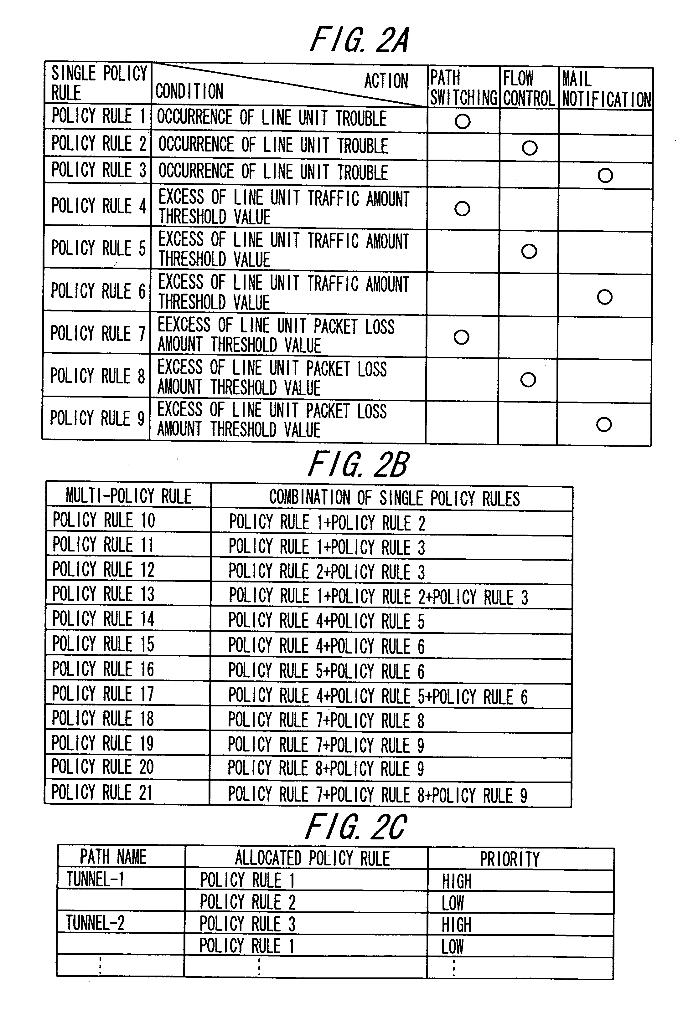
[0154] As an alternative to the second operation example, the network operator utilizes the maintenance / operation terminal connected to the policy server 2 to create multi-policy rules to which plural kinds of priority (e.g., highest, high, middle, and low) are assigned. For example, as shown in FIGS. 2A and (B), priorities of “Low”, “High”, “Highest”, and “Middle” are respectively assigned to multi-policy rules 10 to 13 created by combining single policy rules 1 to 3 belonging to the same condition regarding “Line-basis Trouble Occurs”.

[0155] The network operator additionally designates a network device (e.g., network device of network device ID “172.27.1.1” and interface ID “172.27.50.1”) to which the multi-policy rules with priority are applied.

[0156] Thus, a policy rule registration request is made to the policy management unit 102 through the user interface unit 101. As a result, as in the case of the application of the single policy rule with priority of the second operation...


PUM


Abstract

A policy control device for reflecting a policy rule defined by a condition and an action corresponding to the condition for operation setting of respective network devices present in a network to be managed, according to a transition of operation states of the network, including a storage unit for storing a plurality of multi-policy rules generated in units of combination of at least two single policy rules having different actions on the same condition, together with particular information of a network device to be applied, in such a manner that the plurality of multi-policy rules and the particular information can be updated; and a control unit for applying one of the plurality of multi-policy rules stored in the storage unit for the operation setting of the network device identified, based on the particular information.

Description

CROSS-REFERENCE TO RELATED APPLICATION [0001] This is a continuation of application PCT / JP2003 / 012726, filed on Oct. 3, 2003, now pending, the contents of which are herein wholly incorporated by reference.BACKGROUND OF THE INVENTION [0002] The present invention relates to a network system based on a policy rule, and more particularly to a network system based on a policy rule, capable of suppressing a monotonous increase in single policy rules brought about by an operation and greatly reducing loads on a network operator. [0003] Recently, as Internet access systems, broadband access systems using ADSL (Asymmetric Digital Subscriber Line) and FTTH (Fiber to the Home), etc. have grown popular. Service providers such as a carrier (communication carrier or telecommunications carrier), ISP (Internet Service Provider), and IDC (Internet Data Center) have started to provide services of the broadband access system. As a result, traffic flowing through a network has greatly increased. [0004]...

Claims


Application Information

Patent Timeline
IPC IPC(8): G06F15/173H04L12/24
CPCH04L41/0893H04L41/0894
Inventor OGAWA, KAZUKIKAWAMURA, NOBUHIRONOMIYAMA, SEIJINAKAMURA, KATSUICHIIMAHASE, AKIRA
Owner FUJITSU LTD
Why Eureka
Try Eureka