Lateral force resistance device

a technology of lateral force and resistance device, which is applied in the direction of caissons, building material handling, construction, etc., can solve the problems of increasing the cost of using mat slabs in expansive soil conditions, requiring soil removal altogether, and requiring substantial cost, so as to increase the resistance of the anchoring system, increase the vertical load carrying capacity of helical anchors, and facilitate installation

Inactive Publication Date: 2007-01-04
ST ONGE GENE +2
View PDF19 Cites 35 Cited by
  • Summary
  • Abstract
  • Description
  • Claims
  • Application Information

AI Technical Summary

Benefits of technology

[0005] The present invention is directed to a lateral force resistance device that can be used in connection with helical anchoring systems or other foundation support systems, such as steel pipes, to increase the resistance of the anchoring system to lateral forces exerted by the supported superstructure. The lateral force resistance device of the invention is relatively easily installed over existing ground anchors, and allows a lateral force resistive foundation to be constructed in expansive soils without the soil excavation associated with mat slab systems. The present invention also augments the vertical load carrying capacity of helical anchors and steel piles.

Problems solved by technology

A number of factors, including the diminishing availability of residential lots having good soil conditions and topography, have forced builders of residential housing to consider building sites that are more challenging to build on, and that require special foundations and anchoring systems.
While mat slabs are cost-effective when building on soils that have little or no expansivity, the cost of using mat slabs in expansive soil conditions is substantial, due to the necessity of eliminating the uplifting forces on the slab caused by the expansivity of the soil.
If the soil is highly expansive or corrosive, the soil may need to be removed altogether and replaced with an imported soil material.
Environmental concerns associated with the additional earth work may further add to the cost.
Due to the cost associated with mat slab systems, homebuilders who build in highly expansive soil conditions, and particularly homebuilders in the Las Vegas area, frequently use raised floor foundation systems with helical anchors.
However, such systems have a significant drawback, in that, they provide a relatively low degree of lateral support for the foundation system for resisting lateral forces such as produced by earthquakes or high winds.

Method used


Image

  • Lateral force resistance device
  • Lateral force resistance device
  • Lateral force resistance device

Examples


Embodiment Construction

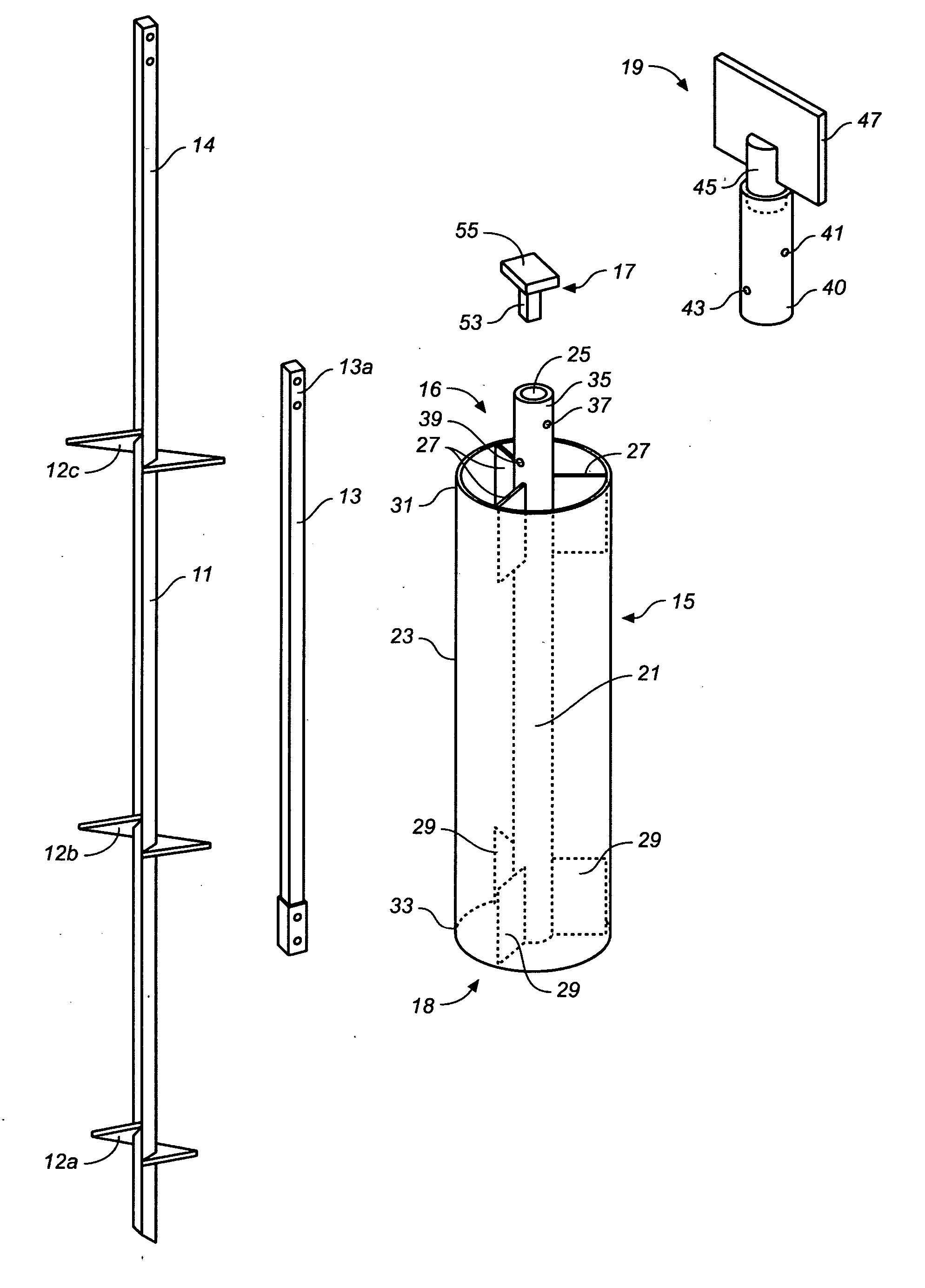
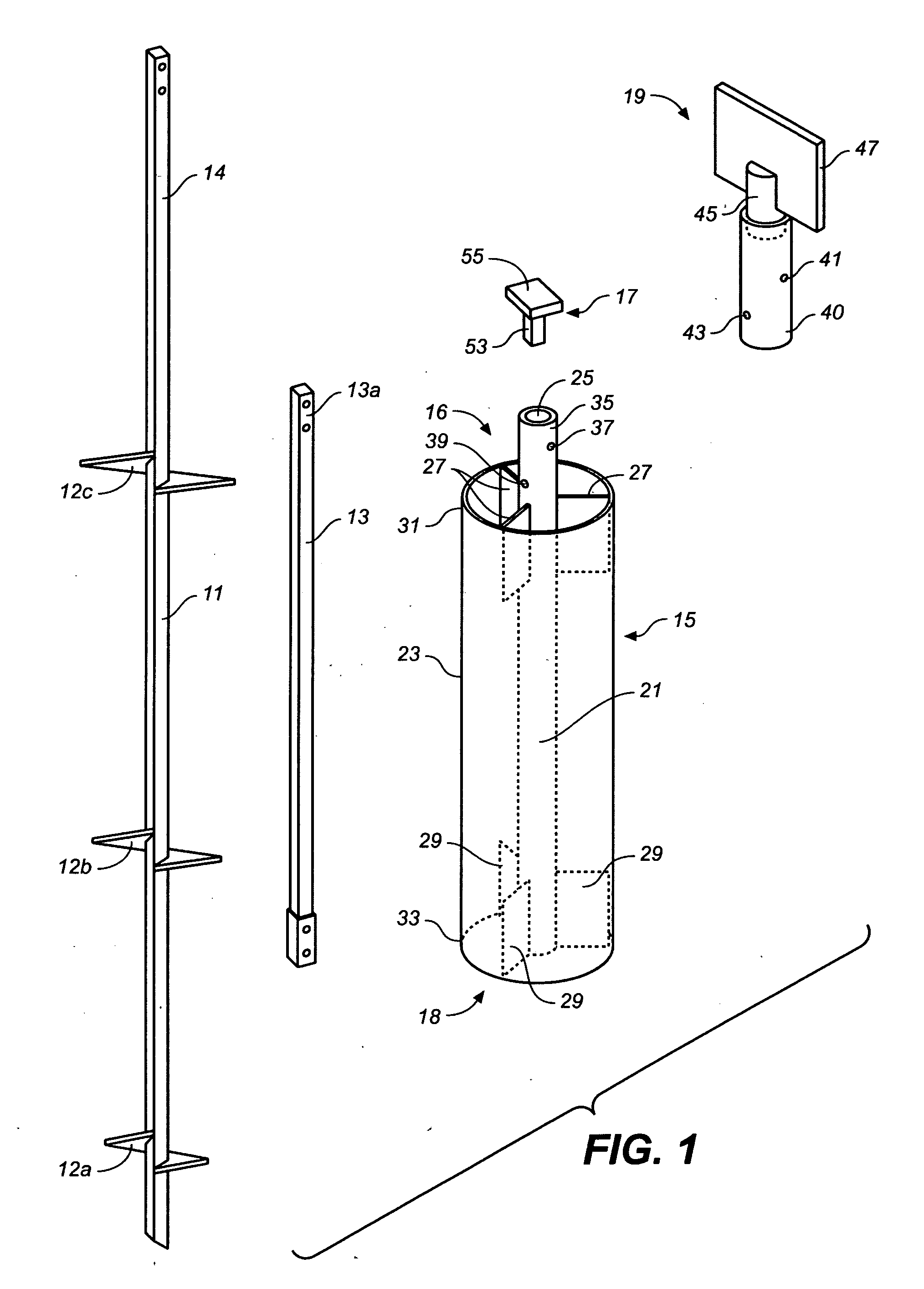
[0017] Lateral force restraining devices in accordance with the present invention, abbreviated herein as “LFRD's,” are intended for use with helical anchors, steel support pipes, and the like (collectively referred to herein as “ground anchors”) used to support above-grade building foundations such as commonly used in expansive soils. Where ground anchors are used, the addition of an LFRD will provide an efficient mechanism and method for efficiently transferring lateral forces, such as generated during earthquakes and high wind conditions, from the building's above-ground superstructure to the soil into which the ground anchors are embedded. The LFRD will also provide the ground anchors with additional vertical load capacity and additional resistance to the tendency of the anchor system to rotate due to unbalanced forces and reaction forces acting on the building superstructure at one end and on the anchor system at the other.

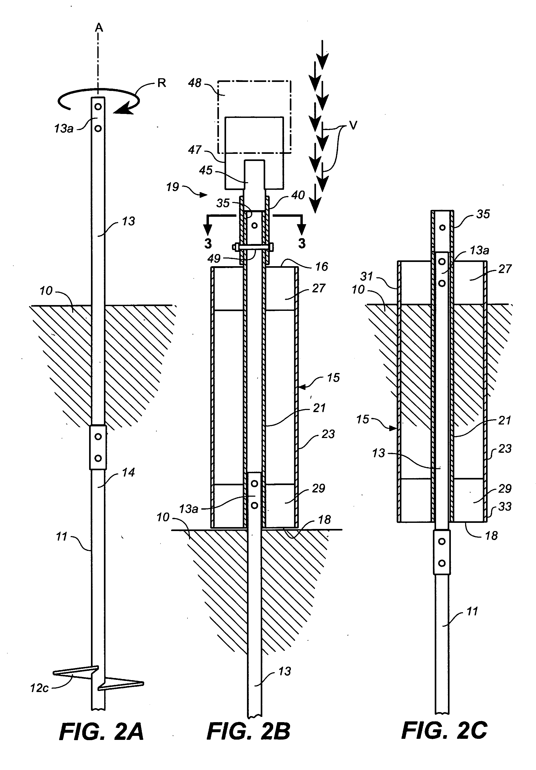
[0018] Referring now to the drawings, FIGS. 1-3 show co...


PUM


Abstract

A lateral force resistance device for a ground achoring system suitably used in expansive soils has an inner sleeve structure and an outer collar connected to the inner sleeve structure by a plurality of load transfer members such as longitudinal load transfer plates. The lateral force resistance device is embedded in the soil over a ground anchor, such as a helical anchor, by sliding the inner sleeve structure of the device over the top end of the anchor and using an embedment method involving vibration, pushing or other technique. The outer collar of the lateral force resistance device provides a relatively large surface area displaced from the inner sleeve structure for providing efficient load transfer to the surrounding soil.

Description

CROSS-REFERENCE TO RELATED APPLICATIONS [0001] This application claims the benefit of U.S. Provisional Application Ser. No. 60 / 680,768 filed May 13, 2005.BACKGROUND OF THE INVENTION [0002] The present invention generally relates to ground anchoring systems for supporting building foundation structures, and more particularly to raised floor foundation systems with helical piles or small diameter pile foundation systems, commonly used at building sites having moderately to highly expansive soil conditions. [0003] A number of factors, including the diminishing availability of residential lots having good soil conditions and topography, have forced builders of residential housing to consider building sites that are more challenging to build on, and that require special foundations and anchoring systems. This includes geographic regions in the United States having highly expansive clay soils, such as the desert areas of Arizona and Nevada. The fast-growing Las Vegas area is an example. T...

Claims


Application Information

Patent Timeline
Patent Type & Authority Applications(United States)
IPC IPC(8): E02D5/74
CPCE02D5/74E02D5/801E02D5/80
Inventor ST. ONGE, GENERHOADES, DANWINSLOW, JAMES
Owner ST ONGE GENE
Why Eureka
Try Eureka