
Tractor with improved valve system

a valve system and rotary equipment technology, applied in the direction of drilling machines and methods, percussion drilling, drilling machine/well accessories, etc., can solve the problems of increasing the risk of damage to the gripper assembly, and increasing the time and cost of rotary equipment. , to achieve the effect of reducing the risk of damage to the gripper assembly, and improving the shifting

Inactive Publication Date: 2007-01-04
WWT NORTH AMERICA HLDG
View PDF64 Cites 8 Cited by
  • Summary
  • Abstract
  • Description
  • Claims
  • Application Information

AI Technical Summary

Benefits of technology

The tractor operates effectively within a broader range of parameters, reducing operational costs and enhancing efficiency in moving equipment, especially in intervention operations and with heavy loads, while minimizing risks of inadvertent movement and damage.

Problems solved by technology

As the drill string is lowered or raised within the borehole, it is necessary to continually add or remove links of drill pipe at the surface, at significant time and cost.
The forward hydraulic thrust on the pistons results in forward thrust on the entire tractor body.
It is more expensive to bring back the rotary equipment than it is to bring in a coiled tubing unit.
However, the coiled tubing unit may not be capable of reaching extended distances within the borehole without the aid of a tractor.
However, it operates most effectively within a limited zone of parameters, including the pressure, weight, and density of the operating fluid, the geometry of the tractor components, and the total weight of the equipment that the tractor must pull and / or push.
This design is problematic because the wheels do not have the ability to provide significant gripping force to move heavier downhole equipment.
Also, the wheels can lose traction in certain conditions, such as in regions including sand.
However, the practice of igniting the perforation guns with e-lines poses the risk of a spark leading to explosion and potential loss of life.
Perforation guns are commonly used in conjunction with rotary drilling equipment, due to the large weight of the guns.
However, the use of rotary equipment is very expensive and time-consuming, due in part to the necessity of assembling and disassembling the portions of drill pipe.
Unfortunately, it is typically not possible to gun-drill the entire length of the shaft (in most applications, the length of a shaft for a downhole tool can be anywhere in the range of 50 to 168 inches).
The distance that a passage can be gun-drilled is limited by (1) the inherent length limitations of known gun-drilling tools, and (2) the limitations imposed by the geometry and material characteristics of the shaft.
This shortage of available “real estate” in the shaft requires higher precision gun-drilling and increases the risk of inadvertent damage to other passages caused by the gun-drilling process.
These problems are exacerbated by the fact that the more flexible materials used for the shaft (e.g., CuBe) are softer, more difficult to drill through, and more prone to damage.
The limitations on the length that passages can be gun-drilled have necessitated forming the shafts from a plurality of shaft portions of reduced length.
Unfortunately, electron beam welding is a very expensive process.
Most conventional welding processes have not been used because they do not facilitate the welding together of thick objects (i.e., the weld does not fuse completely through the objects).

Method used


Image

  • Tractor with improved valve system
  • Tractor with improved valve system
  • Tractor with improved valve system

Examples


Embodiment Construction

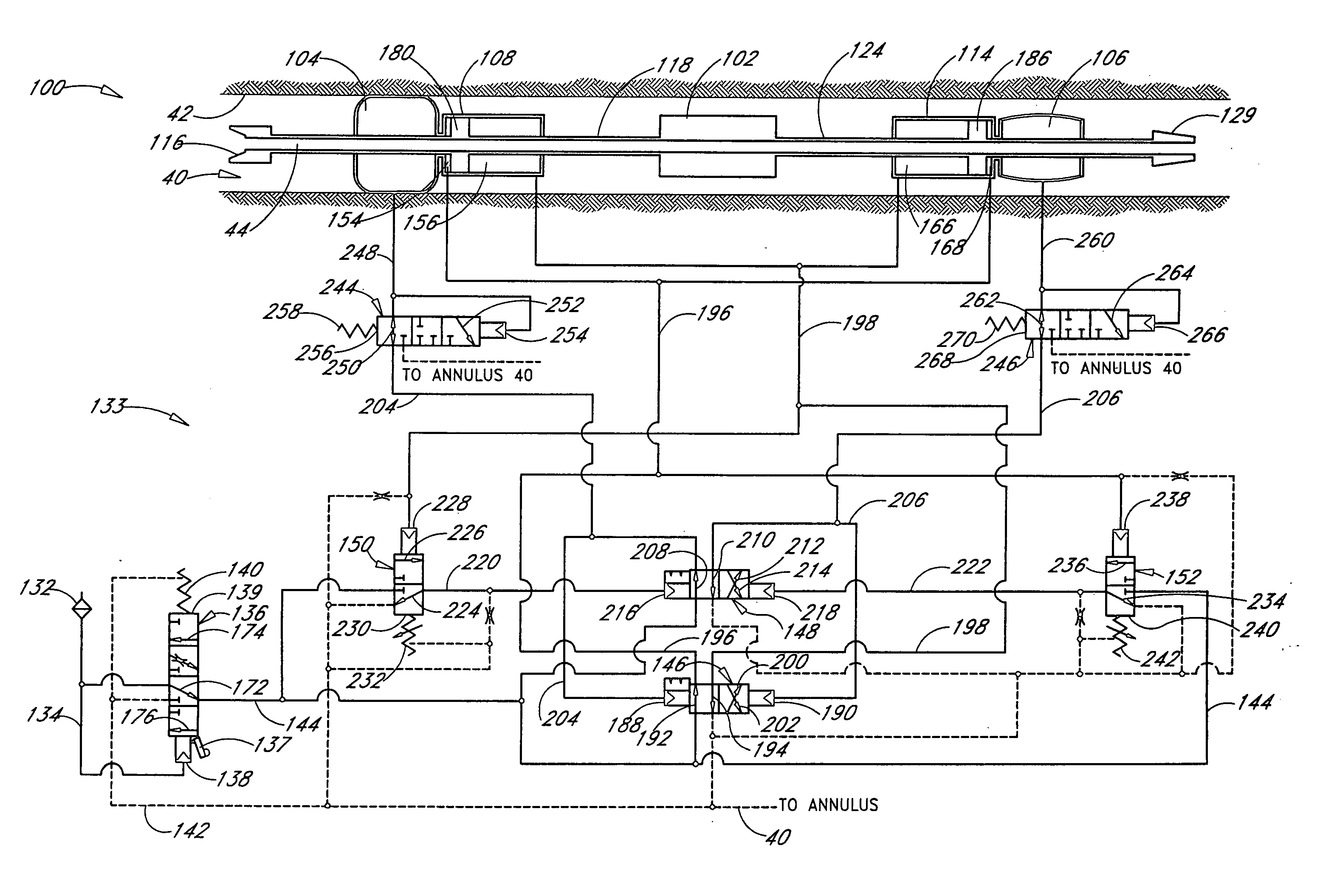
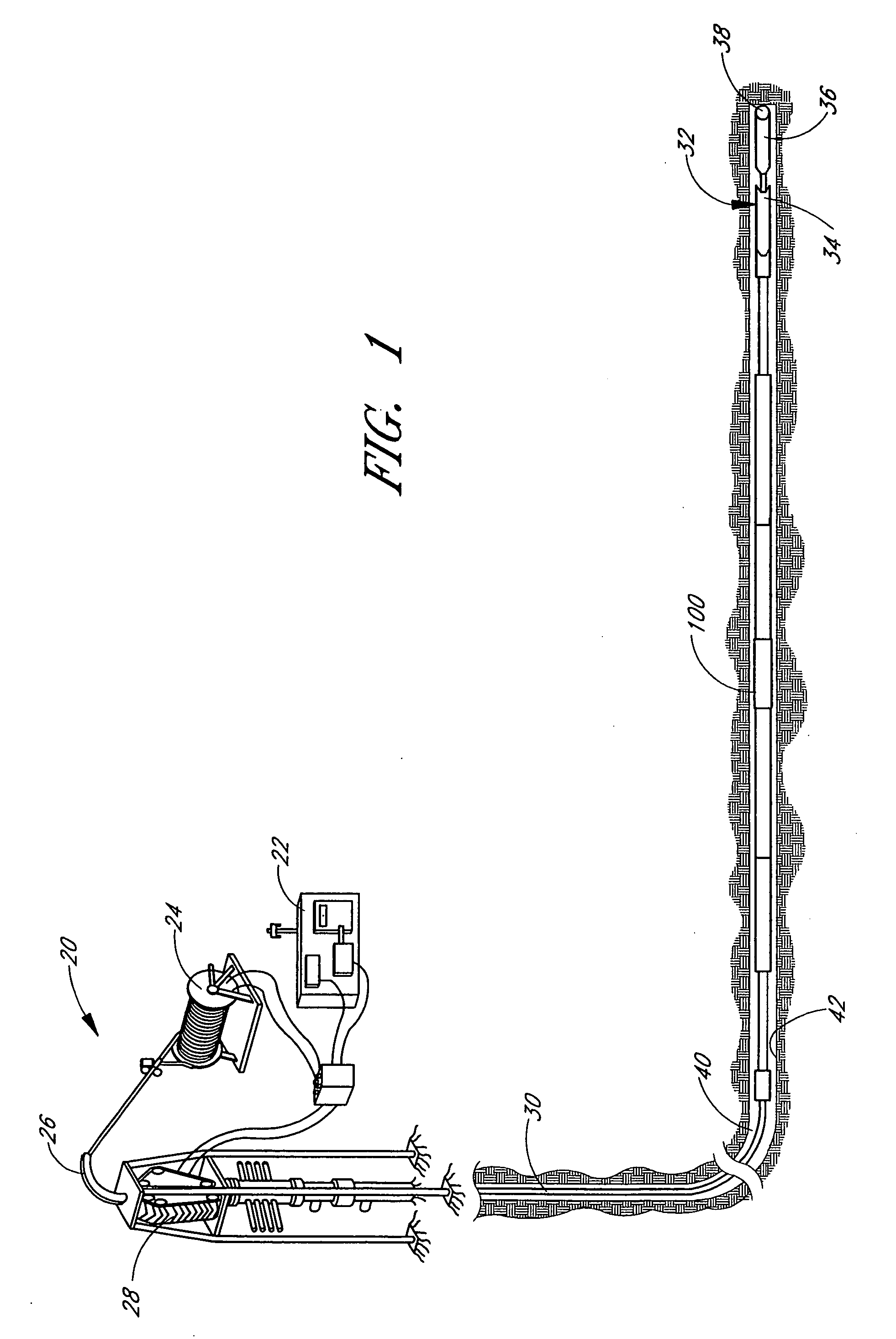
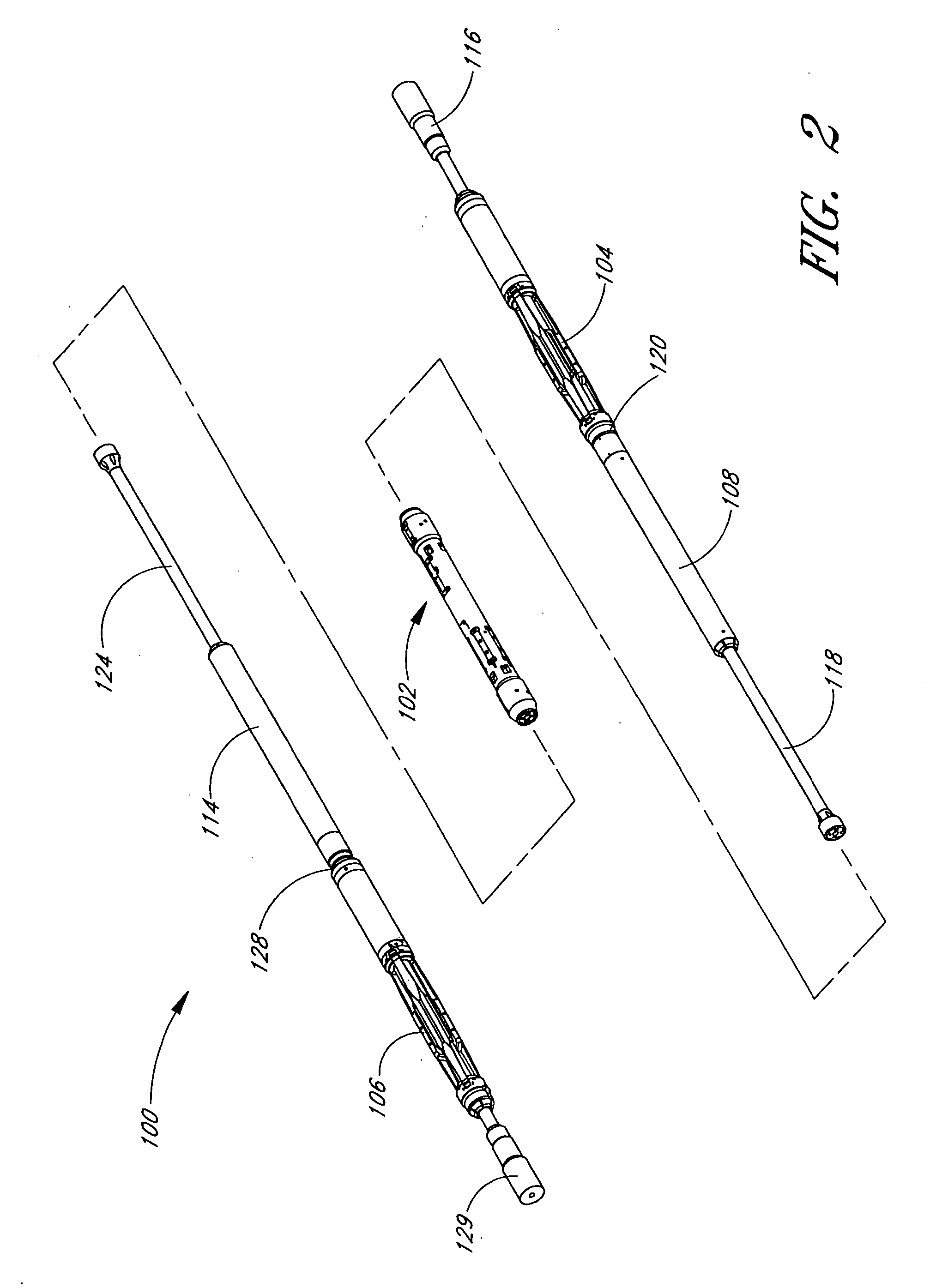
[0084]FIG. 1 shows a hydraulic tractor 100 for moving equipment within a passage, configured in accordance with a preferred embodiment of the present invention. In the embodiments shown in the accompanying figures, the tractor of the present invention may be used in conjunction with a coiled tubing drilling system 20 and adjoining downhole equipment 32. The system 20 may include a power supply 22, tubing reel 24, tubing guide 26, tubing injector 28, and coiled tubing 30, all of which are well known in the art. The tractor 100 is configured to move within a borehole having an inner surface 42. An annulus 40 is defined by the space between the tractor 100 and the inner surface 42 of the borehole.

[0085] The downhole equipment 32 may include various types of equipment that the tractor 100 is designed to move within the passage. For example, the equipment 32 may comprise a perforation gun assembly, an acidizing assembly, a sandwashing assembly, a bore plug setting assembly, an E-line, a...


PUM


Abstract

A hydraulically powered tractor includes an elongated body, two gripper assemblies, at least one pair of aft and forward propulsion cylinders and pistons, and a valve system. The valve system comprises an inlet control valve, a two-position propulsion control valve, a two-position gripper control valve, two cycle valves, and two pressure reduction valves. The inlet control valve spool includes a hydraulically controlled deactivation cam that locks the valve in a closed position, rendering the tractor non-operational. The propulsion control valve is piloted on both ends by fluid pressure in the gripper assemblies. The propulsion control valve controls the distribution of operating fluid to and from the propulsion cylinders, such that one cylinder performs a power stroke while the other cylinder performs a reset stroke. Each end of the gripper control valve is piloted by a source of high-pressure fluid selectively admitted by one of the cycle valves. The gripper control valve controls the distribution of operating fluid to and from the gripper assemblies. The cycle valves are spring-biased and piloted by fluid pressure in the propulsion cylinders, so that the gripper control valve shifts only after the cylinders complete their strokes. The pressure reduction valves limit the pressure within the gripper assemblies. These valves are spring-biased and piloted by the pressure of fluid flowing into the gripper assemblies. Some or all of the valves include centering grooves on the landings of the spools, which reduce leakage and produce more efficient operation. The propulsion control and gripper control valves include spring-assisted detents to prevent inadvertent shifting.

Description

CLAIM FOR PRIORITY [0001] This application is a continuation of and claims priority to co-pending U.S. application Ser. No. 10 / 759,664, filed Jan. 19, 2004, which is a continuation of U.S. application Ser. No. 10 / 004,965, filed Dec. 3, 2001, now U.S. Pat. No. 6,679,341, which claims the benefit under 35 U.S.C. § 119(e) of U.S. Provisional Patent Application Ser. No. 60 / 250,847, filed Dec. 1, 2000.INCORPORATION BY REFERENCE [0002] This application incorporates by reference the entire disclosures of (1) U.S. Pat. No. 6,347,674 to Bloom et al.; (2) U.S. Pat. No. 6,241,031 to Beaufort et al.; (3) U.S. Pat. No. 6,003,606 to Moore et al.; (4) U.S. Pat. No. 6,464,003 to Bloom et al.; (5) U.S. Provisional Patent Application Ser. No. 60 / 250,847, filed Dec. 1, 2000; and (6) U.S. patent application Ser. No. 10 / 004,965, filed on Dec. 3, 2001. BACKGROUND OF THE INVENTION [0003] 1. Field of the Invention [0004] This invention relates generally to tractors for moving equipment within passages. [00...

Claims


Application Information

Patent Timeline
Patent Type & Authority Applications(United States)
IPC IPC(8): E21B4/00E21B4/18E21B23/00E21B23/04
CPCE21B4/18E21B2023/008E21B23/04E21B23/001E21B23/042
Inventor BLOOM, DUANEMOORE, NORMAN BRUCELEVAY, ROBERT
Owner WWT NORTH AMERICA HLDG
Learn More