[0006] The
general purpose of the present invention is to provide a modular display
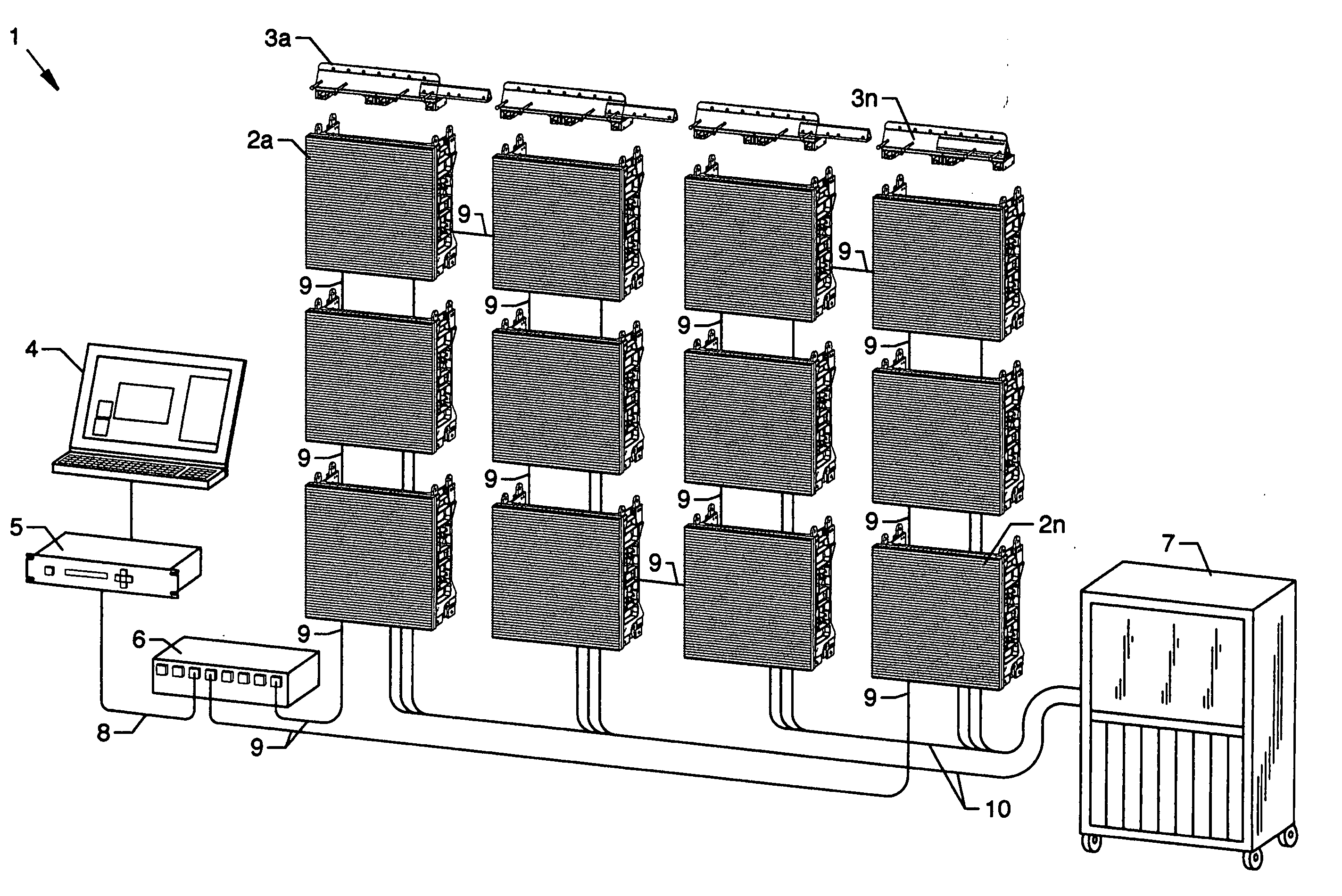
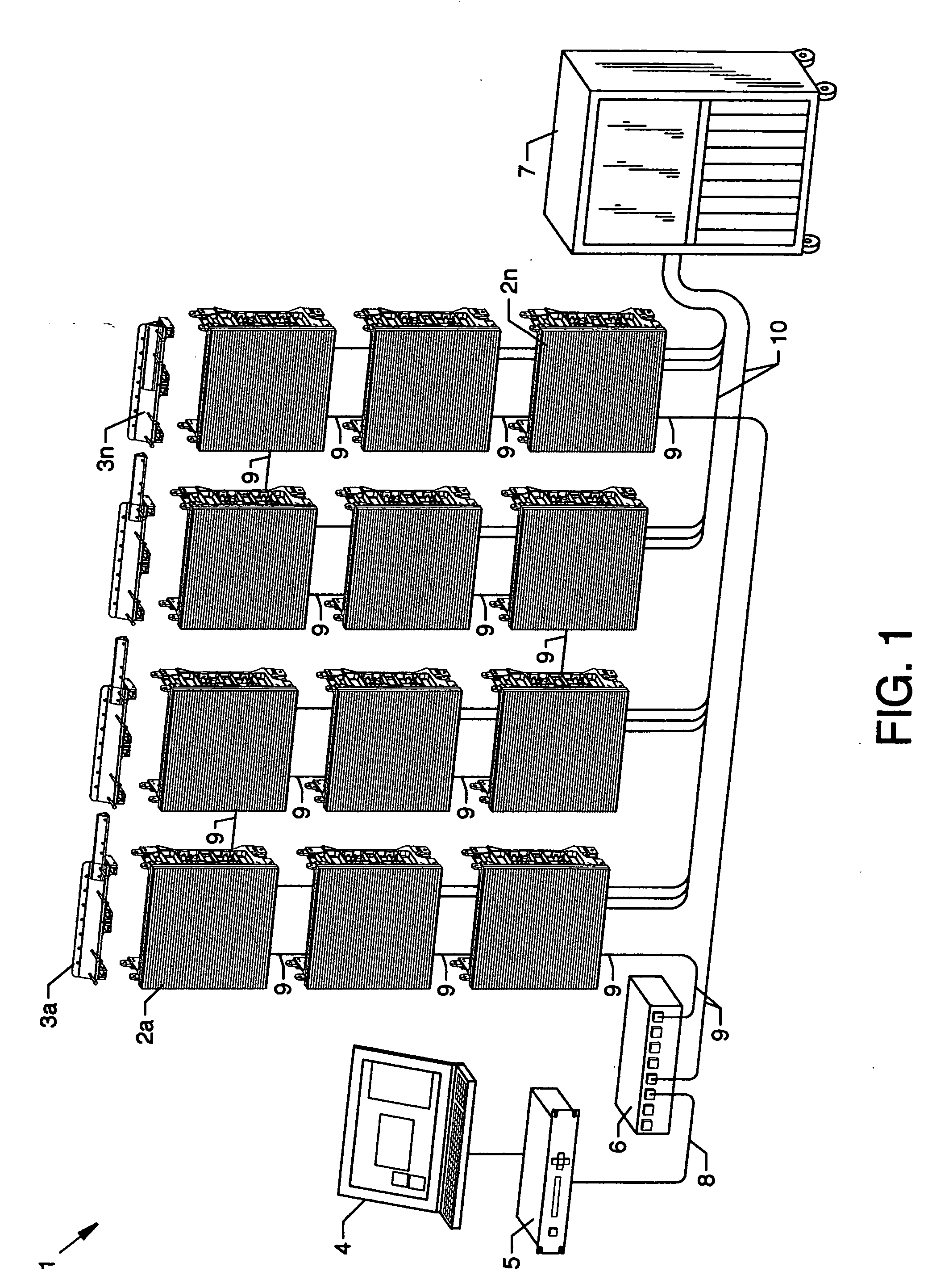
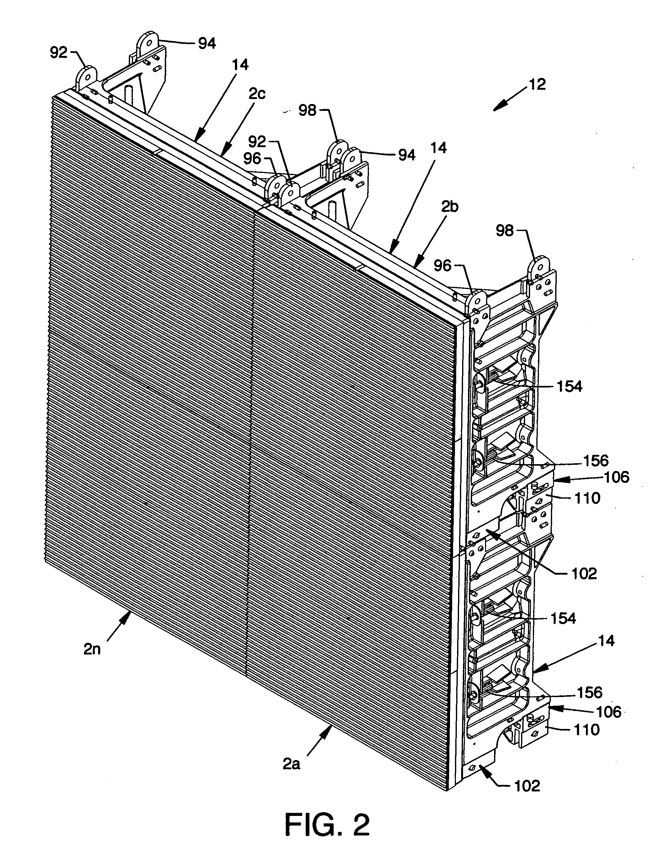
system including stackable electronic display panels and mounting structure which is easily transported and erected. The modular display system, the present invention, includes a plurality of stackable electronic display panels each removably attached with one or more adjacent stackable electronic display panels to form a display. Each individual stackable electronic display panel is constructed of a connector framework and a
light emitting diode (LED) display module attached thereto by a mutually engaging centrally located
LED display module latching system. Each connector framework includes and utilizes connector plates at the top of the connector framework, front connector plate receptors at the bottom of the connector framework having spring-loaded slide pins in alignment thereto, rear connector plate receptors in rear connector assemblies including spring-loaded slide pins and slide pin housings aligned thereto at the bottom and rear of the connector framework, side latch assemblies, side latch keeper assemblies each having an adjustment
cam, a plurality of spring-loaded ball detents and
detent receptors, and other components for removable attachment, alignment and juxtaposition of adjacent stackable electronic display panels. Vertically stacked stackable electronic display panels are attached utilizing the plurality of connector plates along the top of the connector framework in intimate contact and engagement with the front connector plate receptors, the rear connector plate receptors, and the associated spring-loaded slide pins, respectively, at the bottom of another vertically situated overhead stackable electronic display panel. Horizontally situated stackable electronic display panels are connected using side latch assemblies and side latch keeper assemblies having adjustment cams where a latch of each side latch
assembly of one stackable electronic display panel engages the adjustable
cam of each of the side latch keeper assemblies of an adjacent stackable electronic display panel. Arrays of stackable electronic display panels of various configurations can be assembled where attachment occurs both along the
horizontal and vertical aspects of the stackable electronic display panels as just described. Each stackable electronic display panel can be suitably sized for handling by an individual where, for purposes of illustration and example, each stackable electronic display panel could measure 20 inches long by 20 inches wide. Provision is also made for adjustment of each stackable electronic display panel with respect to each other along more than one axis for best alignment of each of the connector frameworks to each other in order to seamlessly position the
LED display modules.
[0007] According to an embodiment of the present invention, there is provided a modular display system wherein a plurality of suitably sized individual stackable electronic display panels can be juxtaposingly stacked or aligned vertically or can be juxtaposingly placed or aligned side by side horizontally or can be juxtaposingly aligned and placed both vertically and horizontally and mutually secured at locations on or near the mutual horizontal sides or vertical sides of the stackable electronic display panels. Rearwardly located connector plate receptors and forwardly located connector plate receptors of an upper stackable electronic display panel are removably attachable to connector plates of a lower stackable electronic display panel and side latches of one stackable electronic display panel engage adjustable cams of side latch keeper assemblies of a horizontally adjacent stackable electronic display panel the combination of which offers stable and sturdy connectibility for a vast arrangement of stackable electronic display panels in a modular display system.
[0016] Still another significant aspect and feature of the present invention is the use of latches in one side panel of a connector framework to engage adjustable cams in a side panel of an adjacent connector framework to provide for vertical adjustability of adjacent connector frameworks with respect to each other vertically along the “Y” axis.

