
Image output apparatus, image output system, and program

a technology of image output and output system, applied in the direction of instruments, computing, electric digital data processing, etc., can solve the problems of image (i.e., ) being too rough and difficult for users to recognize the contents of images, and users may not find the function of printing preview screens beneficial

Inactive Publication Date: 2007-01-04
BROTHER KOGYO KK
View PDF14 Cites 11 Cited by
  • Summary
  • Abstract
  • Description
  • Claims
  • Application Information

AI Technical Summary

Benefits of technology

[0009] Aspects of the present invention are advantageous in that an image output apparatus capable of outputting an image based on data obtained from an external device by using a preferable output unit among a plurality of output units with different functions equipped to the apparatus is provided. Another aspects of the present invention are advantageous in that an image output apparatus capable of outputting an image based on image data obtained from an external device by selectively using an image output unit that requires lower running cost among other image output units that require higher running cost is provided so that outputting the image can be performed cost-effectively.

Problems solved by technology

When the image data is received and the image to be printed is displayed on the LCD, the image (i.e., a so-called “print preview screen”) may be in many cases too rough and too difficult for the user to recognize the contents of the image to be printed, due to a size and a screen resolution of the LCD.
Therefore, when the image data is processed, merely a small part of the image can be shown, and the user may not find the function of the print preview screen beneficial.

Method used


Image

  • Image output apparatus, image output system, and program
  • Image output apparatus, image output system, and program
  • Image output apparatus, image output system, and program

Examples


embodiment

[0053] Hereinafter, referring to the accompanying drawings, a delivery system according to an embodiment of the invention will be described.

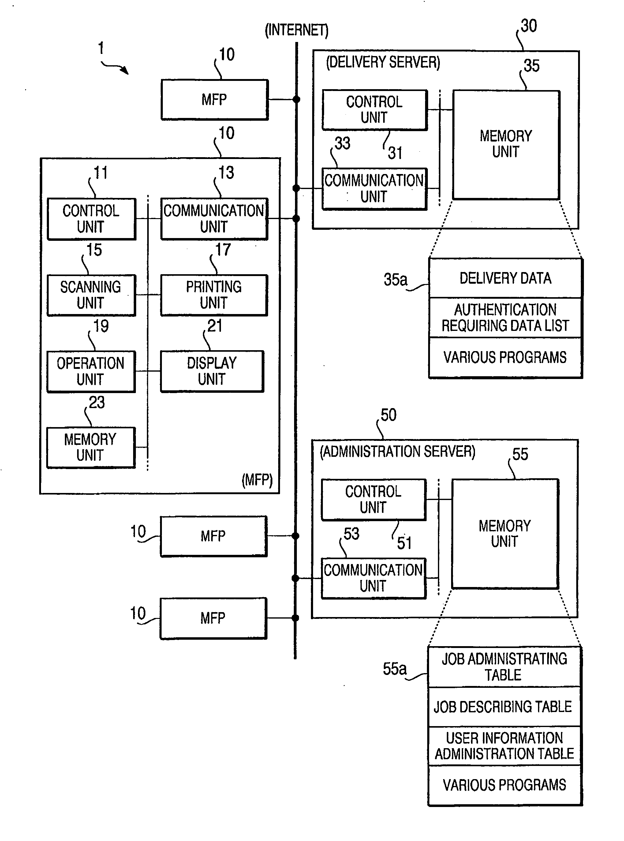
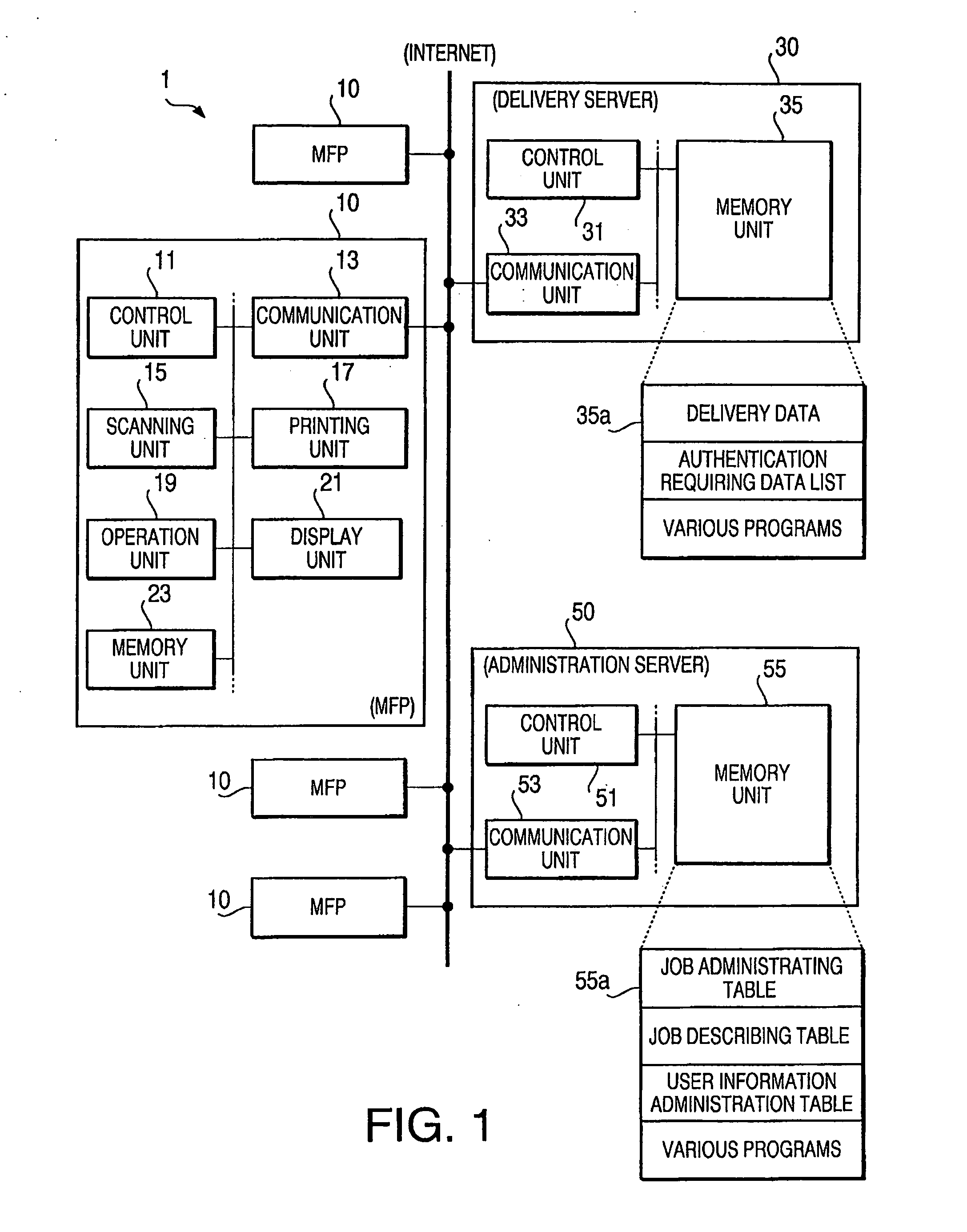
[0054]FIG. 1 shows a block diagram to illustrate a configuration of a delivery system 1 according to an embodiment of the invention. As shown in FIG. 1, the delivery system 1 includes a plurality of digital MFPs 10, a delivery server 30, and an administration server 50, which are respectively connected to a computer network such as the Internet.

[0055] Each of the MFPs 10 includes a control unit 11, a communication unit 13, a scanning unit 15, a printing unit 17, an operation unit 19, a display unit 21, and a memory unit 23. The control unit is configured to control internal operations of the MFP 10. The communication unit 13 is adapted to connect the MFP 10 to the computer network, and is capable of bi-directionally communicating with the other devices in the computer network. The scanning unit 15 is adapted to optically scan an original image...


PUM


Abstract

An image output apparatus, having a first image output device to output a first image, a second image output device, which is capable of outputting a second image in a higher resolution than a resolution of the first image output device, a first obtaining system to obtain first data and locator information indicating a location of second data, which are stored in association with each other in a storing unit, a first controlling system to control outputting the first image based on the first data, a second obtaining system to obtain the second data according to the locator information obtained by the first obtaining system in response to an output instruction given, and a second controlling system to control outputting the second image based on the second data from the second image output device when the second obtaining system obtains the second data, is provided.

Description

CROSS REFERENCE TO RELATED APPLICATION [0001] This application claims priority from Japanese Patent Application No. 2005-185365, filed on Jun. 24, 2005, the entire subject matter of the application is incorporated herein by reference. BACKGROUND [0002] 1. Technical Field [0003] Aspects of the invention relate to an image output apparatus, an image output system, and a program product containing instructions to operate the apparatus and the system. [0004] 2. Related Art [0005] Conventionally, an image output apparatus configured to obtain image data from an external device (for example, a server) via a telephone network or a computer network for printing an image based on the obtained image data is known. This type of image output apparatus may be equipped with a plurality of image output units, each of which has a different manner to output an image, such as an LCD (liquid crystal display) and a printing unit. [0006] An example of such an image output apparatus having an LCD and a p...

Claims


Application Information

Patent Timeline
IPC IPC(8): G06T17/00G06F17/00
CPCH04N1/00204H04N1/00233H04N1/00244H04N1/0044H04N21/2356H04N2201/3205H04N1/32122H04N2201/0039H04N2201/0094H04N2201/3221H04N2201/325H04N1/00488
Inventor AOKI, KAZUMAOHARA, KIYOTAKAMATSUDA, MAKOTO
Owner BROTHER KOGYO KK
Learn More