Beam delivery system for laser dark-field illumination in a catadioptric optical system

a laser dark-field illumination and optical system technology, applied in the field of optical imaging, can solve the problems of difficult practice, system that tries to combine bright-field and dark-field imaging does not perform either mode as well as single-mode design, and exhibits beam delivery problems

Active Publication Date: 2007-01-04
KLA TENCOR TECH CORP
View PDF18 Cites 129 Cited by
  • Summary
  • Abstract
  • Description
  • Claims
  • Application Information

AI Technical Summary

Problems solved by technology

However, this is very difficult to do in practice because different imaging modes have different optical design, software, and system requirements.
In general, systems that attempt to combine bright-field and dark-field imaging do not perform either mode as well as single-mode designs.
Certain of the previous designs exhibit beam delivery issues when performing dark-field imaging.
For example, high NA systems can have dark-field illumination capabilities limited by the central obscuration in the catadioptric optical design.
Such a construction can also limit dark-field illumination and collection angles.
The bright-field illumination and imaging is again limited to those NAs that can pass through a slot in the center of the focusing mirror elements, again limiting dark-field illumination and collection angles.
Collection angles are also limited to the range of angles within the NA of the objective.
A major drawback of this approach is the Fourier distribution collected by the optics is highly directional, where only higher angles are collected from one side of the scattered and diffracted light distribution.
The problem with this technique is that small amounts

Method used


Image

  • Beam delivery system for laser dark-field illumination in a catadioptric optical system
  • Beam delivery system for laser dark-field illumination in a catadioptric optical system
  • Beam delivery system for laser dark-field illumination in a catadioptric optical system

Examples


Embodiment Construction

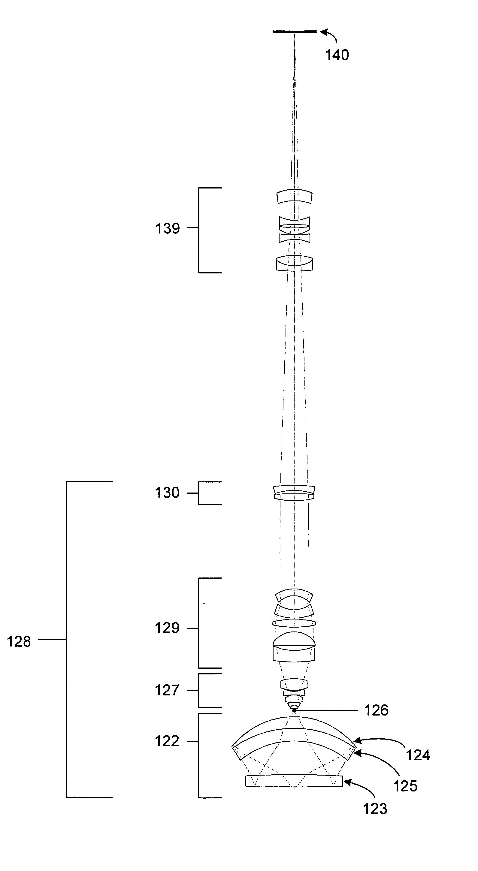
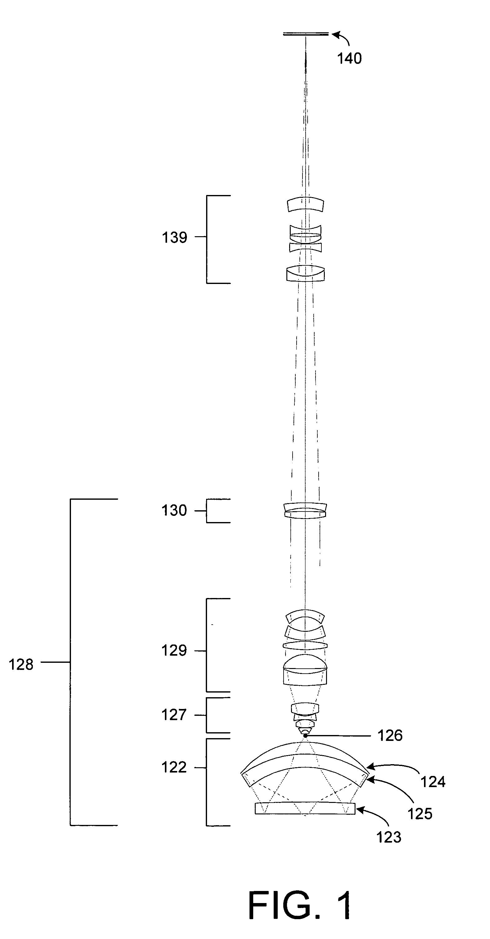
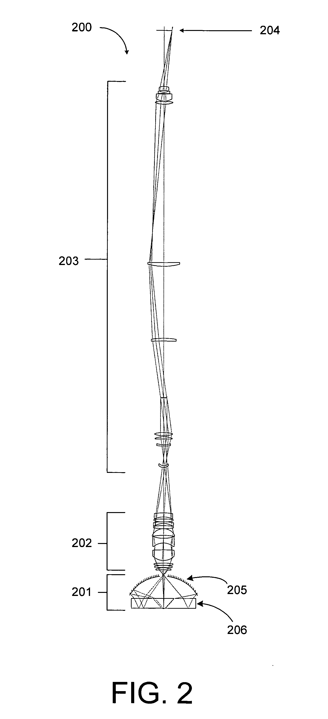
[0029] The present design is an apparatus that can support both broad-band bright-field inspection and laser dark-field inspection techniques without compromising the performance of either technique. To accomplish this enhanced dual-mode inspection capability, both inspection techniques use the same imaging system, detection system, and autofocus system. The illumination systems employed differ from those previously available, and a Fourier filter or other pupil aperture is employed for normal incidence laser dark-field modes. A detector with a suitable dynamic range may be employed in the detection system to handle the high dynamic range signals produced by the normal incidence dark-field inspection technique.

[0030] The present design is useful for beam delivery for illuminating surfaces for optical inspection with laser sources. The design is particularly suited for use with optical systems that have a central obscuration which blocks light from traversing along the optical axis ...


PUM


Abstract

A method and apparatus for inspecting a specimen are provided. The apparatus comprises a primary illumination source, a catadioptric objective exhibiting central obscuration that directs light energy received from the primary illumination source at a substantially normal angle toward the specimen, and an optical device, such as a prism or reflective surface, positioned within the central obscuration resulting from the catadioptric objective for receiving further illumination from a secondary illumination source and diverting the further illumination to the specimen. The method comprises illuminating a surface of the specimen at a variety of angles using a primary illumination source, illuminating the surface using a secondary illumination source, the illuminating by the secondary illumination source occurring at a substantially normal angle of incidence; and imaging all reflected, scattered, and diffracted light energy received from the surface onto a detector.

Description

BACKGROUND OF THE INVENTION [0001] 1. Field of the Invention [0002] The present invention relates generally to the field of optical imaging, and more specifically to catadioptric optical systems used for bright-field and dark-field optical inspection applications. [0003] 2. Description of the Related Art [0004] Many optical and electronic systems exist to inspect surface features for defects such as those on a partially fabricated integrated circuit or a reticle. Defects may take the form of particles randomly localized on the surface, scratches, process variations such as under etching, and so forth. Such techniques and apparatus are well known in the art and are embodied in various commercial products such as many of those available from KLA-Tencor Corporation of San Jose, Calif. [0005] Several different imaging modes exist for optical inspection. These include bright-field, and a variety of dark-field imaging modes. Each of these imaging modes can detect different types of defect...

Claims


Application Information

Patent Timeline
IPC IPC(8): G02B17/00
CPCG02B21/10G02B17/0856
Inventor CHUANG, YUNG-HOARMSTRONG, J. JOSEPH
Owner KLA TENCOR TECH CORP
Why Eureka
Try Eureka