DC demagnetization method and apparatus for magnetic recording medium and magnetic transfer method and apparatus

a demagnetization method and magnetic recording medium technology, applied in the field of dc demagnetization methods and apparatus for magnetic recording mediums and magnetic transfer methods and apparatuses, can solve the problems of difficult to obtain uniform output over the entire surface of the target disk, difficulty in solving problems such as unsolved, and reduction of the c/n ratio of reproduced signals on the target disk, so as to achieve uniform magnetic transfer, uniform magnetization, and no variation in the strength of applied magnetic fields

Inactive Publication Date: 2007-01-04
FUJIFILM CORP +1
View PDF5 Cites 4 Cited by
  • Summary
  • Abstract
  • Description
  • Claims
  • Application Information

AI Technical Summary

Benefits of technology

[0057] As described above, the present invention makes it possible to obtain uniform magnetization over almost the entire surface without much variation in the strength of the applied magnetic field relative to media coercivity during DC demagnetization.
[0058] Also, the present invention makes it possible to perform uniform magnetic transfer over almost the entire surface without much variation in the strength of the applied magnetic field relative to media coercivity or in media magnetization during magnetic transfer.

Problems solved by technology

However, with conventional techniques such as those described in Japanese Patent Application Laid-open Nos. 2001-28127 and 2002-237031, the strength of the applied magnetic field relative to media coercivity on the disk surface varies during DC demagnetization or magnetic transfer, causing a problem of reduction in the C / N ratio of reproduced signals on the target disk.
However, Japanese Patent Application Laid-open No. 2001-28127 and the like provide no guideline for a range of practically acceptable variations in the magnetic field strength, and thus the problem remains unsolved.
On the other hand, Japanese Patent Application Laid-open No. 2002-237031 does not take magnetic viscosity and the number of magnetic field applications into consideration, and thus it is difficult to obtain uniform output over the entire surface of the target disk.

Method used


Image

  • DC demagnetization method and apparatus for magnetic recording medium and magnetic transfer method and apparatus
  • DC demagnetization method and apparatus for magnetic recording medium and magnetic transfer method and apparatus
  • DC demagnetization method and apparatus for magnetic recording medium and magnetic transfer method and apparatus

Examples


examples i

[0134] (Production of Slave Disk)

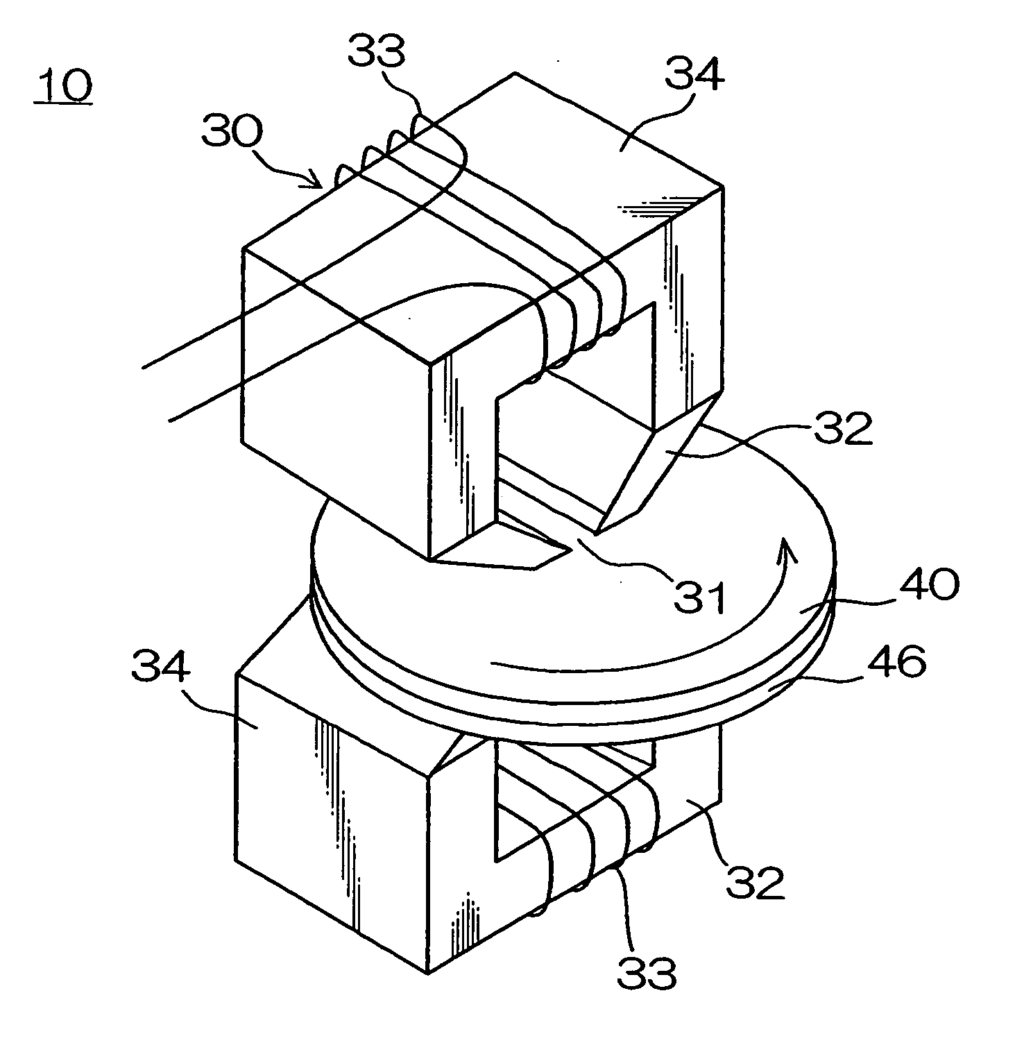
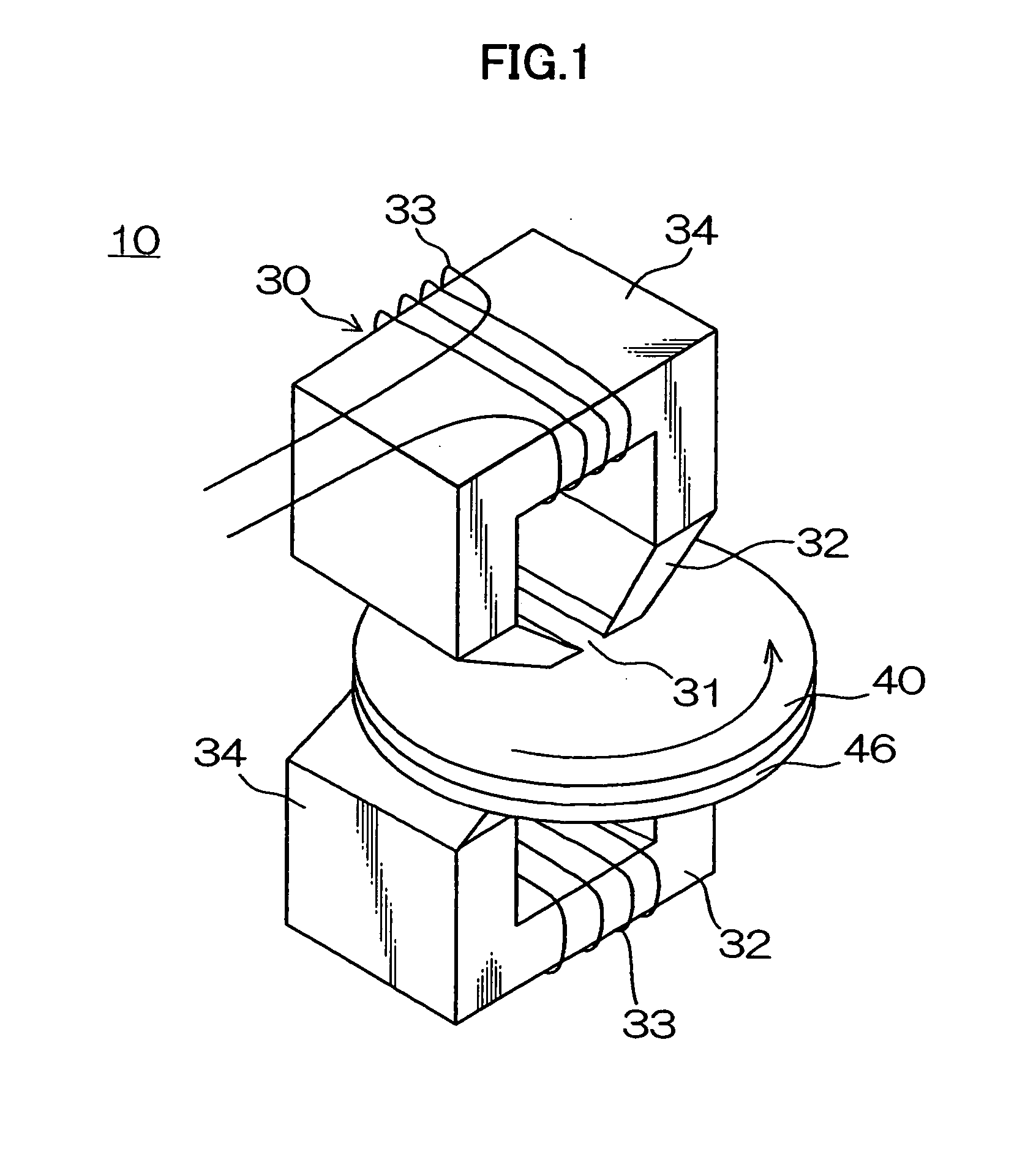
[0135] A slave disk 40 was produced under the conditions described below, initial DC magnetization was performed using the magnetic field generating device, and signals transferred to the slave disk 40 was evaluated.

[0136] The slave disk 40 was a thin-film hard disk of glass. A 95-mm outside-diameter (3.5 inch type) hard disk with a magnetic layer of CoCrPt 25 nm in film thickness and 5.7 T (4500 Gauss) in flux density Ms was produced using a vacuum deposition apparatus as follows: pressure was reduced to 1.33×10⁻⁵ pa (10−7 Torr) at room temperature, argon gas was introduced, and a glass plate was heated to 200° C. at 0.4 Pa (3×10⁻⁵ Torr).

example i-3 (examples i-3-1 and i-3-2)

and Comparative Example I-3

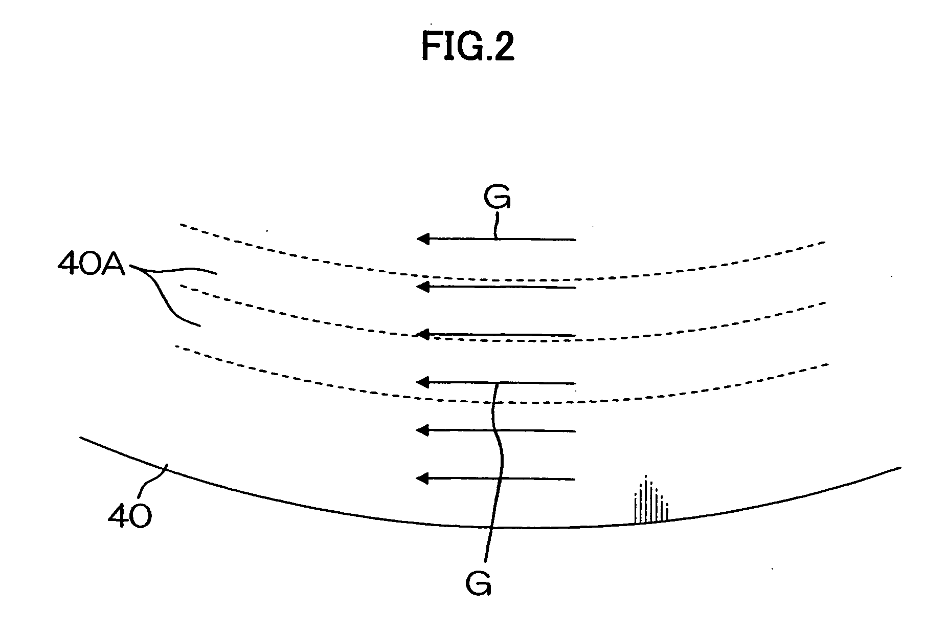
[0153] (DC Demagnetization Method According to Example I-3-1)

[0154] A magnetic field was applied to the slave disk 40 by moving an electromagnet 80 such as shown in FIG. 10 outward from the inner part of the slave disk 40. The following conditions of magnetic field application were used: with the rotational speed of the slave disk 40 kept at 60 rpm, the applied magnetic field strength was set at 358 kA / m (4500 Oe) when the electromagnet 80 was located at a radius of 35 mm, increased gradually as the electromagnet 80 moved toward a radius of 70 mm, and set at 517 kA / m (6500 Oe) when the electromagnet 80 was located at a radius of 70 mm.

[0155] (DC Demagnetization Method According to Example I-3-2)

[0156] A magnetic field was applied to the slave disk 40 using the electromagnet 80 such as shown in FIG. 10. With the applied magnetic field strength fixed at 557 kA / m (7000 Oe), the electromagnet 80 was moved from a radius of 35 mm toward a radius of 70 mm. The...

example i-4

[0162] (Production of Master Disk for Magnetic Transfer)

[0163] A 95-mm outside-diameter (3.5 inch type), disc-shaped master disk 46 for magnetic transfer was produced using a vacuum deposition apparatus as follows: pressure was reduced to 1.33×10⁵ pa (10−7 Torr) at room temperature, argon gas was introduced, and a FeCo film 200 nm in thickness was formed on a silicon substrate at 0.4 Pa (3×10⁻⁵ Torr). On the master disk 46, 150 radial line patterns were provided at equal intervals (intervals of 2.4°) between radii 35 mm and 70 mm. The coercivity Hc of the master disk 46 was 8 kA / m (100 Oe) and flux density Ms was 28.9 T (23000 Gauss).

[0164] (Magnetic Transfer Method)

[0165] The slave disk 40 subjected to DC demagnetization in a manner similar to example I-1-1 was placed in close contact with the master disk 46 and a magnetic field was applied in the direction opposite the magnetization of the slave disk 40 using a device with permanent magnets 60 placed on both sides as shown in F...


PUM

PropertyMeasurementUnit
circumferential angleaaaaaaaaaa
coercivity Hcaaaaaaaaaa

Abstract

According to the present invention, since the applied magnetic field strength is controlled so as to fall between maximum magnetic field strength×0.7 and the maximum magnetic field strength over almost an entire surface of the magnetic recording medium, there is not much variation in the strength of the applied magnetic field relative to media coercivity during DC demagnetization, which makes it possible to obtain uniform magnetization over almost the entire surface.

Description

BACKGROUND OF THE INVENTION [0001] 1. Field of the Invention [0002] The present invention relates to a DC demagnetization method and apparatus for a magnetic recording medium as well as to a magnetic transfer method and apparatus. More particularly, it relates to a DC demagnetization method and apparatus for a magnetic recording medium which are suitable for transferring magnetic information patterns such as format information from a master disk to a magnetic disk used for a hard disk drive and the like and a magnetic transfer method and apparatus which use a magnetic recording medium initialized by the DC demagnetization method. [0003] 2. Description of the Related Art [0004] Regarding magnetic disks (hard disks) used for hard disk drives which has sprung into wide use recently, generally format information and address information are written into them after the magnetic disks are delivered from magnetic disk makers to drive makers, but before they are incorporated into the drives....

Claims


Application Information

Patent Timeline
Patent Type & Authority Applications(United States)
IPC IPC(8): G11B5/86G11B5/03
CPCB82Y10/00G11B5/865G11B5/743G11B5/0245
Inventor FUJINAMI, TATSUYANAGAO, MAKOTOKOMATSU, KAZUNORI
Owner FUJIFILM CORP
Why Eureka
Try Eureka