
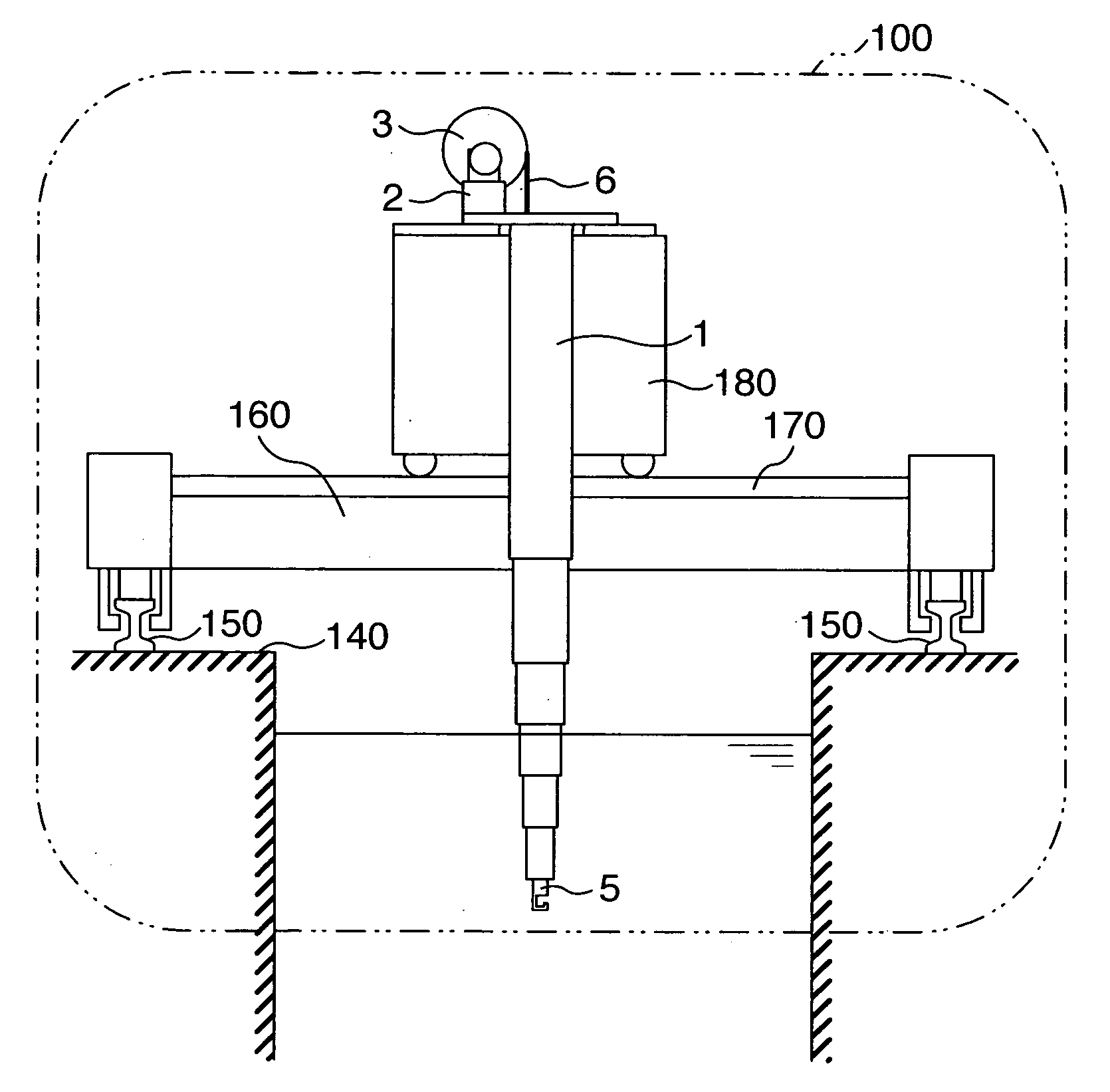
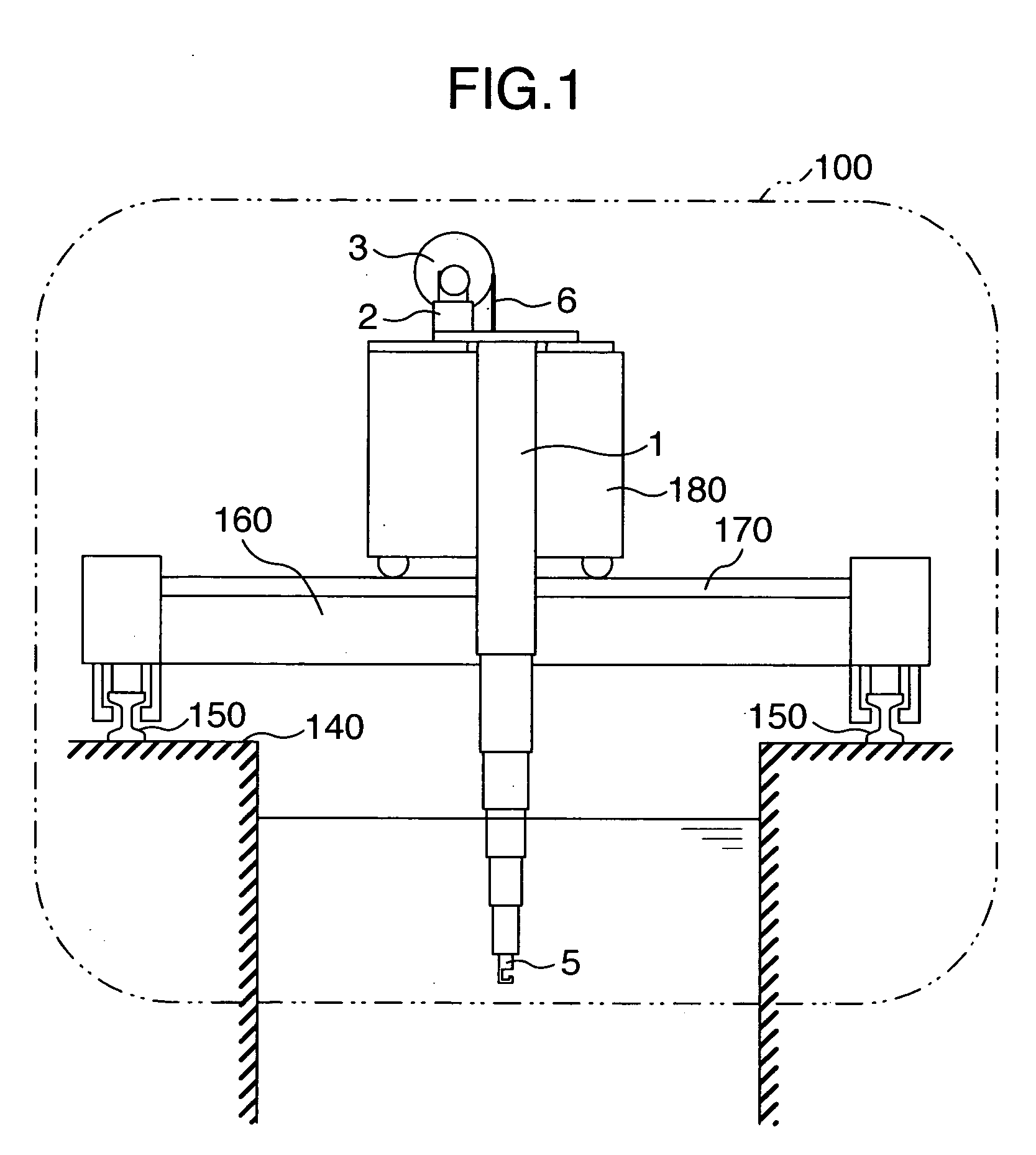
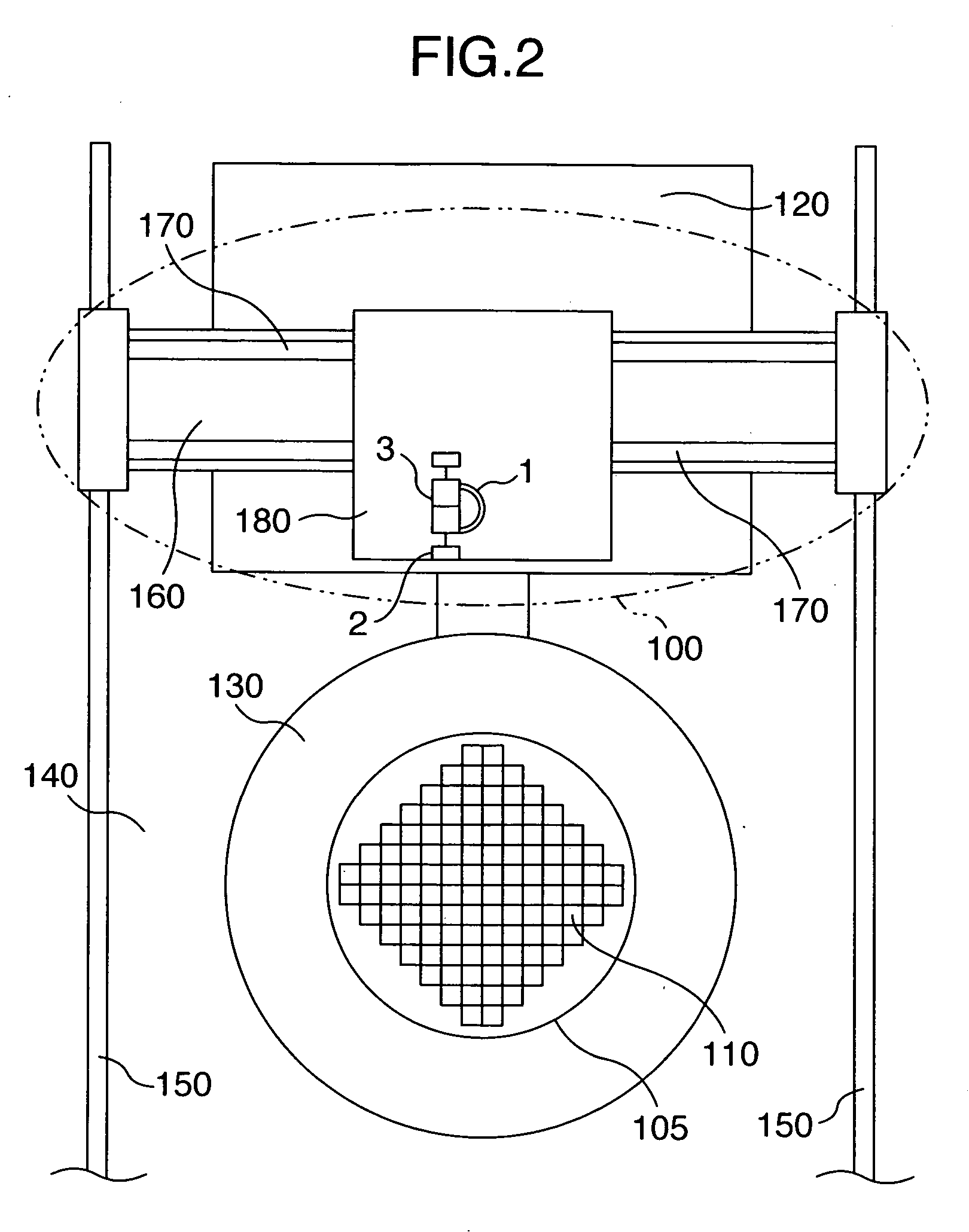
Fuel grasping device and fuel exchanger

Inactive Publication Date: 2007-01-04
HITACHI LTD
View PDF0 Cites 2 Cited by
  • Summary
  • Abstract
  • Description
  • Claims
  • Application Information

AI Technical Summary

Benefits of technology

[0010] If projections (stoppers) for preventing pulling out contact each other at a joint position between upper and lower ones of the tubular members of the conventional telescopic tube so that the tubular members of the conventional telescopic tube are prevented from being pulled out from each other, a vertical velocity of the tubular members of the telescopic tube needs to be decreased to prevent a damage of the projections causing a drop of the tubular members of the telescopic tube when passing the joint position (the projections contact each other), so that the operation for exchanging the fuel is delayed.
[0012] Further, even if all of the tubular members of the telescopic tube are simultaneously ejected or retracted through single rope with the pulleys at the upper and lower ends of the tubular members of the telescopic tube, the length of the rope to be wound also needs to be sufficient for extending from the winding drum to the fuel gripper at the lowermost position thereof, so that the time period for winding the rope deteriorates the speeding up. Further, in the structure in which the pulleys are arranged at the upper and lower ends of the tubular members of the telescopic tube, all of the tubular members bear a weight and a feeding force applied from the wire by the driver and are simultaneously ejected when the tubular members of the telescopic tube descends. On the other hand, when the tubular members of the telescopic tube ascends by pulling up the fuel gripper through the rope, the tubular members of the telescopic tube is prevented by gravitation from ascending instantly, and the fuel gripper contacts the projection (stopper) of the innermost one of the tubular members to be moved upward to be followed by that the tubular members contact sequentially the respective projections to be moved upward, so that when passing the joint position (the projections contact each other) during the operation of the fuel exchanger, the ascending velocity is decreased.
[0013] An object of the present invention is to decrease a time period for telescopic motion of the telescopic tube for the fuel grasping device so that the fuel exchanging operation is accelerated.
[0016] According to the invention, since an impingement between projections for preventing pulling-out at a joint position between the tubular members of the telescopic tube and an application of a plurality of winding drums different in diameter from each other and a plurality of ropes for the respective tubular members of the telescopic tube do not need to be considered, a time period for telescopic motion of the telescopic tube can be decreased.

Problems solved by technology

Further, the increase of the length of the rope to be wound causes an increase in diameter of the winding drum, so that problems of increase in weight of the structure and of increase in volume for mounting the telescopic tube occur.
Further, even if all of the tubular members of the telescopic tube are simultaneously ejected or retracted through single rope with the pulleys at the upper and lower ends of the tubular members of the telescopic tube, the length of the rope to be wound also needs to be sufficient for extending from the winding drum to the fuel gripper at the lowermost position thereof, so that the time period for winding the rope deteriorates the speeding up.

Method used


Image

  • Fuel grasping device and fuel exchanger
  • Fuel grasping device and fuel exchanger
  • Fuel grasping device and fuel exchanger

Examples


first modified embodiment

[0041] the above described embodiment of the invention is explained with making reference to FIG. 5. In FIG. 5, hoisting electric motors 2a and 2b for the respective winding drums 3g and 3h are driven synchronously to move vertically the tubular members 1a-1f.

[0042] Sets of the winding drums and hoisting electric motors are arranged in a circumferential direction of the tubes to connect the wire ropes extending from the respective winding drums to the tubular member 1b as the second one from the uppermost one of the tubular members of the telescopic tube, so that diameter of the wire ropes can be decreased, and the pair of the drivers and the pair of the wire ropes improve safety. The other structure and action are similar to those of the embodiment of FIGS. 1-4.

second modified embodiment

[0043] the embodiment of the invention shown in FIGS. 1-4 is explained with making reference to FIGS. 6 and 7.

[0044] For preventing a rotation between the conventional tubular members on an axis of the tube, rails are attached to inner surfaces of the tubular members along the axis of the tube, and pairs of rail guides between which the rail is held in the circumferential direction are attached to outer surfaces of the tubular members. The rails held between the rail guides prevent the tubular members from rotating with respect to each other.

[0045] On the contrary, in the modified embodiment as shown in FIG. 6, the diameters of the pulleys 9a and 9b mounted on the tubular member 1b are increased to reach the tubular members 1a and 1c adjacent radially, and slits 70a and 70b are formed on the tubular members 1a and 1c adjacent radially to interfere with the pulleys so that the pulleys 9a and 9b and the slits 70a and 70b are used as the rails and rail guides.

[0046] The other tubular...


PUM


Abstract

A fuel grasping device in a nuclear reactor has a telescopic tube including a plurality of tubular members combined with each other to enable a telescopic motion, a fuel gripper arranged at a lower end of the telescopic tube to grasp the fuel assembly for the nuclear reactor, and a driver for winding up and down a rope to perform the telescopic motion vertically. Rotatable members are mounted on the tubular members. A pulling-out preventing projection is used at the joint position of the tubular members. A deceleration of the vertical velocity at the joint position of the tubular members is not necessary so that a time period for the vertical movement can be decreased.

Description

BACKGROUND OF THE INVENTION [0001] The present invention relates to an equipment for a nuclear power plant, particularly to a fuel grasping device for grasping in a nuclear reactor a fuel and a blade guide to be handled and a fuel exchanger for transferring the grasped fuel and blade guide. [0002] A nuclear electric plant as the nuclear power plant is equipped with the fuel exchanger as the equipment for the nuclear power plant, which fuel exchanger runs along a well pool in the nuclear reactor and a spent fuel storage pool. [0003] The fuel exchanger has a travel carriage running along the well pool in the nuclear reactor and the spent fuel storage pool, a transverse travel carriage running on the travel carriage to transverse each of the pools, and the fuel grasping device mounted on the transverse travel carriage. [0004] Such fuel exchanger is used in operations for exchanging and rearranging a fuel assembly, on which operations the blade guide or fuel assembly for the nuclear rea...

Claims


Application Information

Patent Timeline
IPC IPC(8): G21C19/00
CPCB66C13/06G21C19/18G21Y2002/202G21Y2004/504G21Y2002/304G21Y2004/30G21Y2004/501G21Y2002/204Y02E30/30
Inventor NAGANO, SHINJIIWAMA, KUNIHIKOAZUMAISHI, RYOUJIKOMETANI, YUTAKAOOMORI, SHINYA
Owner HITACHI LTD
Learn More