Electrical connector housing alignment feature

a technology of electrical connectors and housings, applied in the direction of connection contact member materials, coupling device connections, engagement/disengagement of coupling parts, etc., to achieve the effect of minimizing shear stress and minimizing the movement of the contact assembly

Active Publication Date: 2007-01-04
FCI AMERICAS TECH LLC
View PDF80 Cites 57 Cited by
  • Summary
  • Abstract
  • Description
  • Claims
  • Application Information

AI Technical Summary

Benefits of technology

[0006] The invention may include providing protrusions formed as part of or attached to a receptacle housing in the housing's contact assembly receiving area. The location of each protrusion may correspond to a location of a well in a contact assembly. Each well may be located between dual beams of ground contact terminals and may be disposed to receive ground contacts of a plug connector. Thus when the contact assembly is received in the receptacle housing, each protrusion is received in a corresponding well. The protrusions may be sized to provide a snug fit to help minimize the movement of the contact assembly.
[0007] Additionally, the protrusions may be located to ...

Problems solved by technology

A problem, however, may occur if, for example, a load is applied on the ...

Method used


Image

  • Electrical connector housing alignment feature
  • Electrical connector housing alignment feature
  • Electrical connector housing alignment feature

Examples


Embodiment Construction

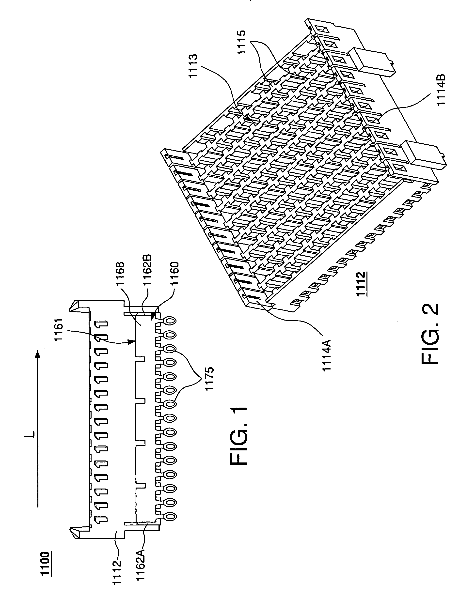
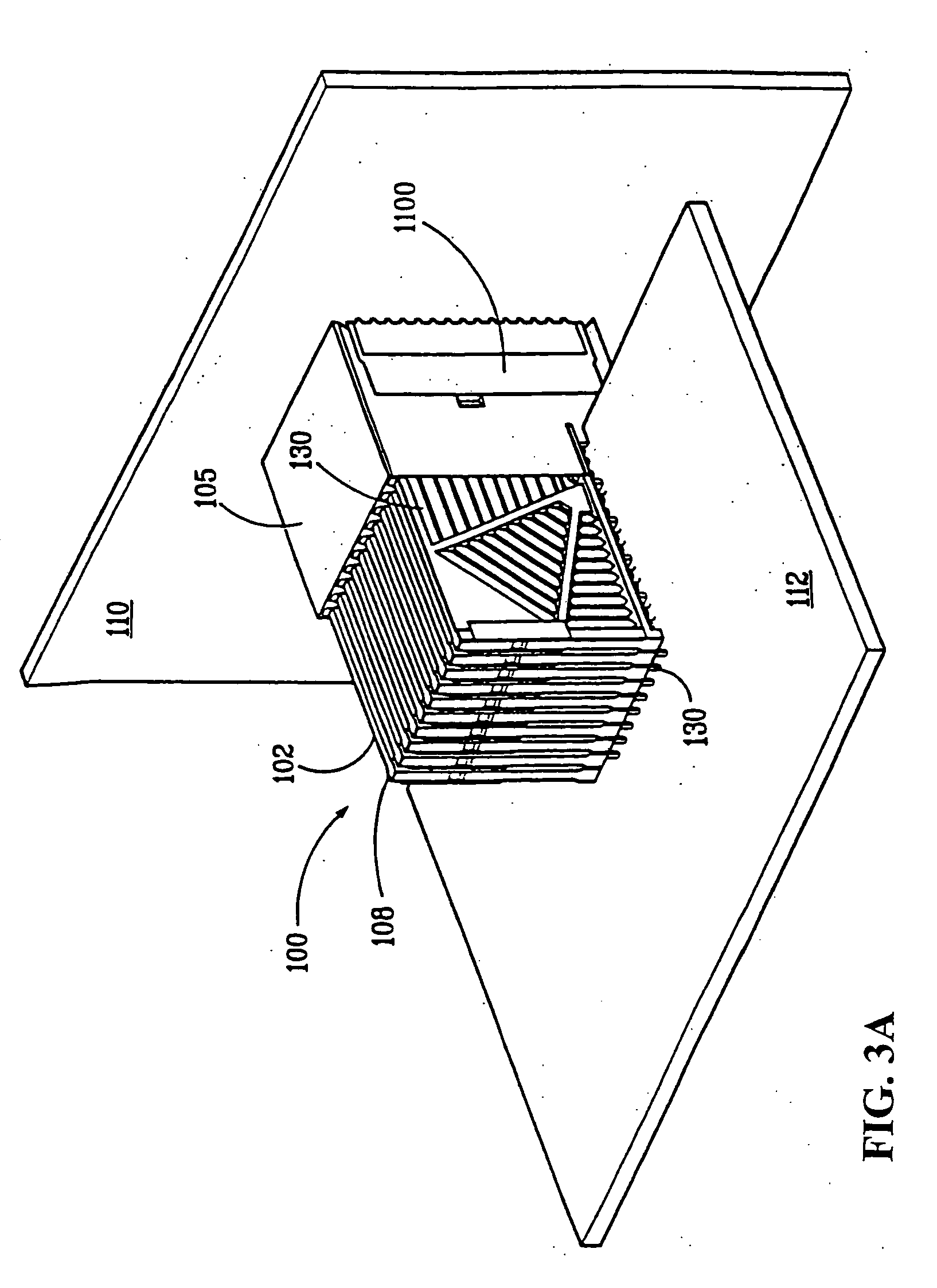
[0027]FIG. 3A is a perspective view of a backplane system 110 having an exemplary right angle electrical connector 100 in accordance with an embodiment of the invention. However, the invention may take other forms such as a vertical or horizontal electrical connector. As shown in FIG. 3A, connector 100 comprises a plug connector 102 and receptacle connector 1100.

[0028] Plug connector 102 comprises housing 105 and a plurality of lead assemblies 108. The housing 105 is configured to contain and align the plurality of lead assemblies 108 such that an electrical connection suitable for signal communication is made between a first electrical device 112 and a second electrical device 110 via receptacle connector 1100. In one embodiment of the invention, electrical device 110 is a backplane and electrical device 112 is a daughter card. Electrical devices 110 and 112 may, however, be any electrical device without departing from the scope of the invention.

[0029] As shown, the connector 102...


PUM


Abstract

An electrical connector receptacle housing is provided that includes protrusions in the housing's contact assembly receiving area. The location of each protrusion corresponds to a location of a well formed in a contact assembly between dual beams of ground contacts. When the contact block is received in the housing, each protrusion is received in a corresponding well. The protrusions may be sized to provide a snug fit as the contact block is received in the receptacle housing. The protrusions thus help minimize the movement of the contact block.

Description

CROSS REFERENCE TO RELATED APPLICATIONS [0001] The present invention relates to U.S. patent application having Ser. No. 10 / 232,883 filed Aug. 30, 2002, entitled “Electrical Connector Having A Cored Contact Assembly[,]” which is assigned to the assignee of the present application and hereby incorporated herein by reference in its entirety.FIELD OF THE INVENTION [0002] The invention relates to electrical connectors and specifically to improved alignment features in electrical connector housings. BACKGROUND OF THE INVENTION [0003] An electrical connector may electrically connect to another electrical connector or to a device such as, for example, a motherboard or a daughter card. Additionally, a receptacle connector, for example, connected to a motherboard also may be electrically connected to a plug connector that is connected to a daughter card, resulting in an electrical connection between the motherboard and daughter card. A receptacle connector may include one or more receptacle c...

Claims


Application Information

Patent Timeline
IPC IPC(8): H01R13/514H01R12/71
CPCH01R13/5045H01R13/6587H01R13/516H01R13/64H01R12/73
Inventor MARSHALL, ROBERT E.
Owner FCI AMERICAS TECH LLC
Why Eureka
Try Eureka