Servo-controlled pneumatic pressure oscillator for respiratory impedance measurements and high-frequency ventilation

a technology of impedance measurement and impedance oscillator, which is applied in the direction of respirators, functional valve types, diagnostic recording/measure, etc., can solve the problems of large subject cooperation, inconvenient operation, and often load-dependent non-physiologic flows that can be generated (typically less than 0.2 l/s)

Inactive Publication Date: 2007-01-11
TRUSTEES OF BOSTON UNIV
View PDF6 Cites 23 Cited by
  • Summary
  • Abstract
  • Description
  • Claims
  • Application Information

AI Technical Summary

Problems solved by technology

While straightforward, this technique has several technical and clinical drawbacks.
Moreover, only non-physiologic flows can be generated (typically less than 0.2 L / s) that are often load-dependent unless a closed-loop design is employed.
Finally, this approach requires considerable subject cooperation.
Despite the ability of such systems to produce high fidelity flow waveforms, they can be extremely inefficient due to mechanical friction and stick-slip effects between the piston and cylinder.
Regardless of the method employed to acquire respiratory impedance data, a more vexing problem is the ability to make oscillatory measurements while the lungs are maintained at a specified mean volume or pressure.

Method used


Image

  • Servo-controlled pneumatic pressure oscillator for respiratory impedance measurements and high-frequency ventilation
  • Servo-controlled pneumatic pressure oscillator for respiratory impedance measurements and high-frequency ventilation
  • Servo-controlled pneumatic pressure oscillator for respiratory impedance measurements and high-frequency ventilation

Examples


Embodiment Construction

[0029] The present invention will be described in connection with preferred embodiments; however, it will be understood that there is no intent to limit the present invention to the embodiments described herein. On the contrary, the intent is to cover all alternatives, modifications, and equivalents as may be included within the spirit and scope of the present invention, as defined by the appended claims.

[0030] For a general understanding of the present invention, reference is made to the drawings. In the drawings, like reference have been used throughout to designate identical or equivalent elements. It is also noted that the various drawings illustrating the resent invention are not drawn to scale and that certain regions have been purposely drawn disproportionately so that the features and concepts of the present invention could be properly illustrated.

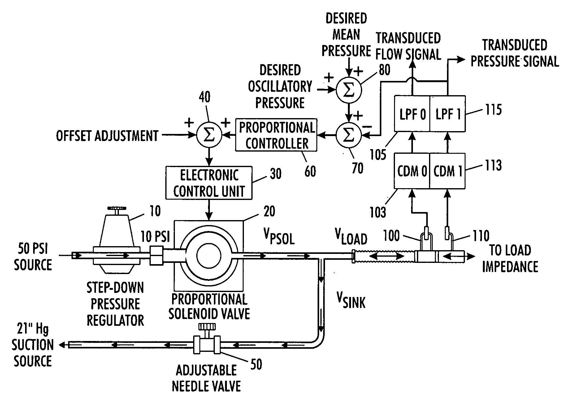
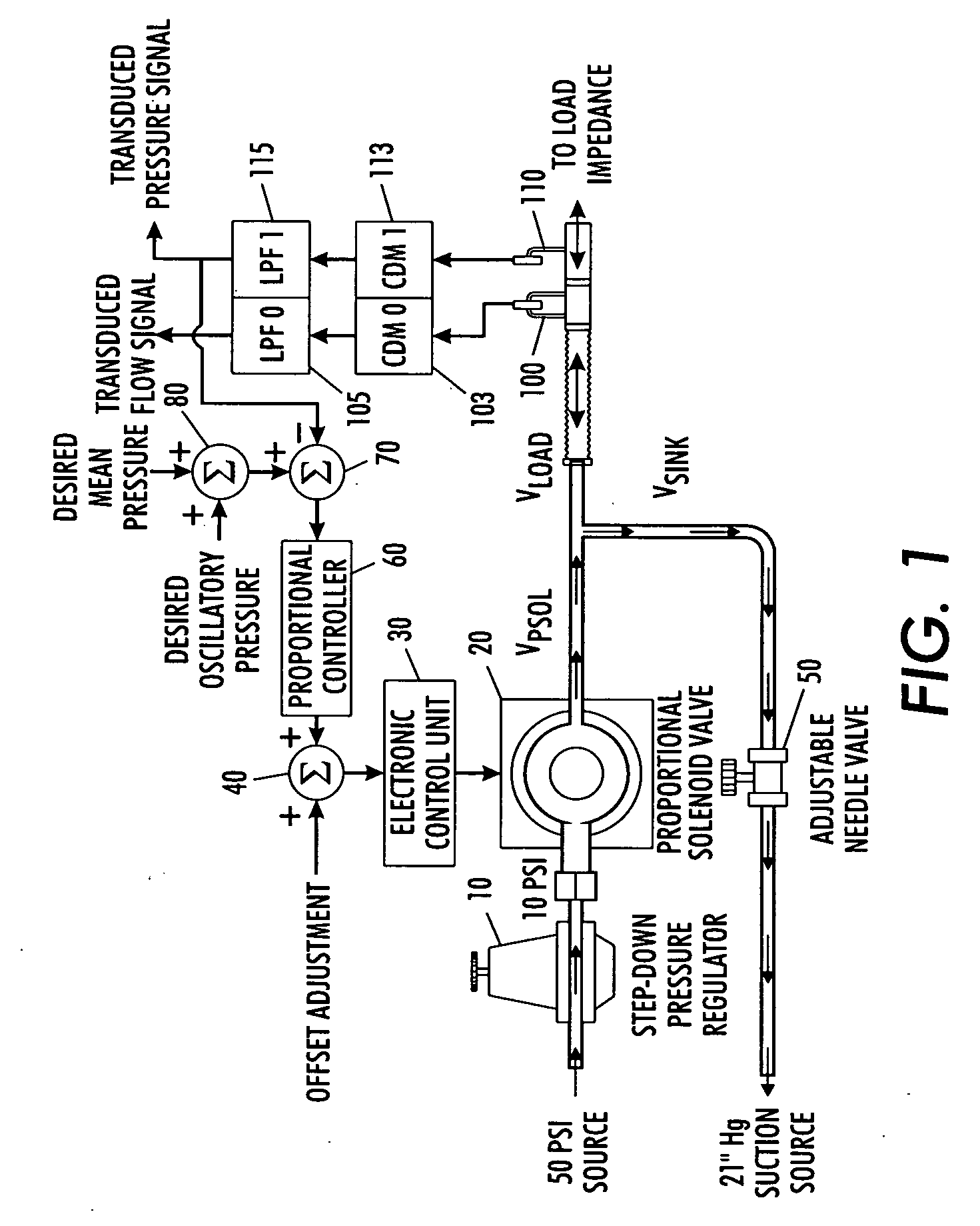
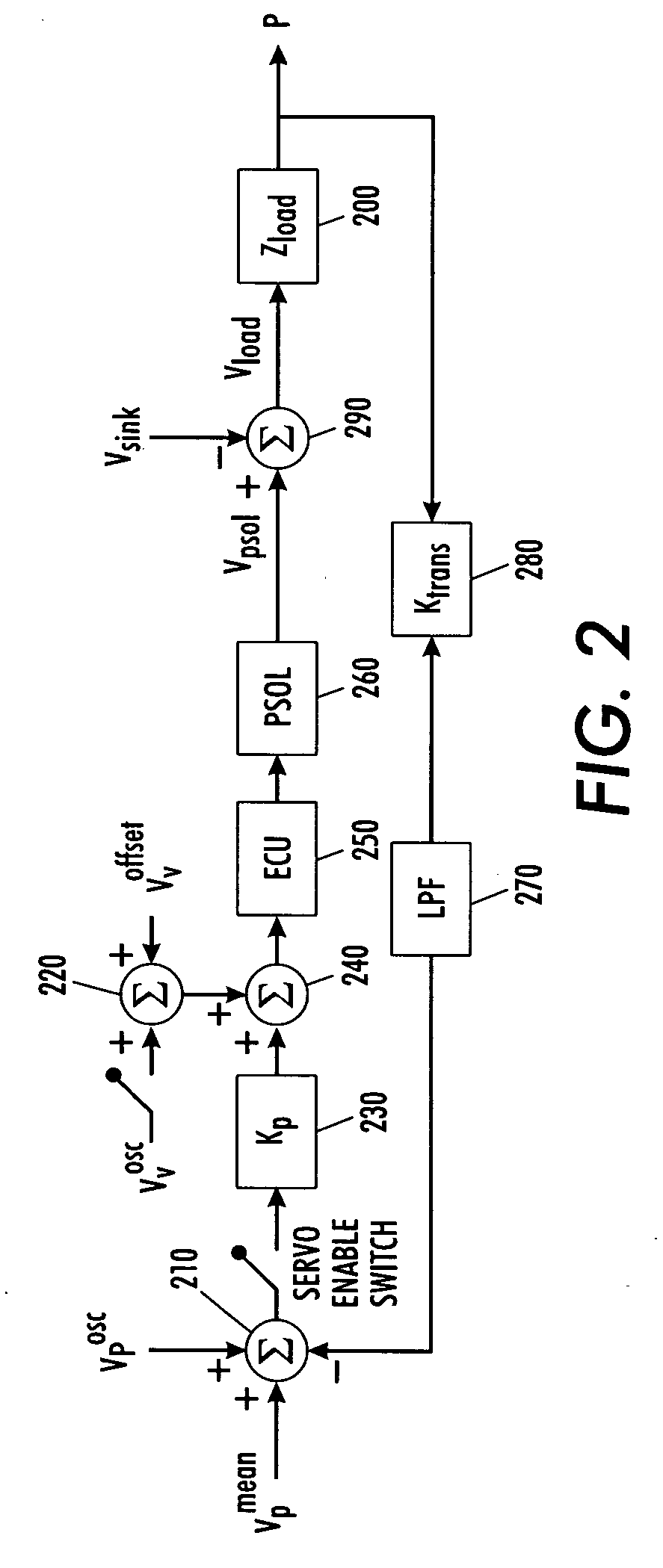
[0031] As noted above, it is desirable to make oscillatory measurements while the lungs are maintained at a specified mean volu...


PUM


Abstract

A pneumatic ventilation system delivers high amplitude, low frequency oscillatory flows while maintaining the load impedance at a specified mean pressure, thereby accurately controlling mean airway pressure, oscillation amplitude, and frequency content allowing use in applications to optimize high frequency ventilation protocols in patients. The pneumatic ventilation system includes a pneumatic pressure oscillator based on a proportional solenoid valve to provide forced oscillatory excitations to a respiratory system over a bandwidth suitable for mechanical impedance measurements and high frequency ventilation.

Description

PRIORITY INFORMATION [0001] The present patent application claims priority under 35 U.S.C. §119 from U.S. Provisional Patent Application Ser. No. 60 / 534,306 filed on Jan. 5, 2004. The entire contents of U.S. Provisional Patent Application Ser. No. 60 / 534,306 filed on Jan. 5, 2004 are hereby incorporated by reference.GOVERNMENT RIGHTS NOTICE [0002] The present invention was made with Government Support under Grant Numbers R01 HL050515 and R01 HL062269 awarded by the National Institutes of Health and Grant Number BES-9309426 awarded by the National Science Foundation. The Government has certain rights in the present invention.FIELD OF THE PRESENT INVENTION [0003] The present invention is directed to a device for measuring respiratory input impedance to assess the dynamic mechanical status of the lungs with also providing high frequency ventilation to the lungs. More particularly, the present invention is directed to a device for measuring the respiratory input impedance over low frequ...

Claims


Application Information

Patent Timeline
Patent Type & Authority Applications(United States)
IPC IPC(8): F16K17/00A61B5/085A61M16/00A61M16/20
CPCA61M16/0096A61M2016/0036A61M16/203A61M2230/65A61M2230/40Y10T137/7725
Inventor KACZKA, DAVID W.LUTCHEN, KENNETH R.
Owner TRUSTEES OF BOSTON UNIV
Why Eureka
Try Eureka