Maintenance platform

a platform and maintenance technology, applied in the field of maintenance platforms, can solve the problems of inability to dismount and remount suspended access equipment after full hardening, inability to meet or fully meet the requirements of construction designs that have existed, and double unfavorable mounting methods, so as to prevent cables from twisting, increase the stability of each separate handrail, and contribute to the safety of maintenance personnel

Inactive Publication Date: 2007-01-11
AEROCONCEPT ING FUR LUFTFAHRTECHN & FASERVERBUNDTECH MBH
View PDF9 Cites 61 Cited by
  • Summary
  • Abstract
  • Description
  • Claims
  • Application Information

AI Technical Summary

Benefits of technology

[0022] The present construction is also rendered suitable for use by virtue of suspension from at least two points, of which at least one is attached to the hub in front of the rotor plane by means of the cable suspension member. The cable suspension member rotates with the rotor, without the support and safety cable rotating as well. This prevents the cables from twisting.
[0023] Another advantageous feature of the maintenance platform are the handrails on the sub-platforms. Said handrails on the separate platforms have pipes inside which a cable is guided with longitudinal displaceability, said cable interconnecting the handrails of a plurality of sub-platforms with each other. Due to its longitudinal displaceability, the cable is able to compensate for any changes in spacing between the handrails of different platforms as a result of the sub-plafforms being swiveled. Two cables are preferably provided for this purpose and overlap in the area of one of the swivel joints, preferably of the swivel joint facing away from the tower. In addition to compensating for changes in spacing, the cables also have the advantage that they significantly increase the stability of each separate handrail, and in this way contribute to the safety of the maintenance personnel on the maintenance platform.

Problems solved by technology

The increasing size of wind turbines, not only with respect to hub height, but also to the specific dimensions of the blades, combined with the desire for offshore wind power generation gives rise inevitably to requirements for suspended access equipment that cannot be met or fully met with the construction designs that have existed hitherto.
The disadvantage of suspending the access equipment from the rotor blades themselves is that, in order to treat the next rotor blade, the suspended access equipment must be dismounted and remounted again after the rotor has been rotated to the next position.
If repair work needs to be carried out in sections where the mounting for the suspended access equipment is located, this type of mounting is doubly unfavorable.
Since maintenance and repair work on blades mainly involves lamination and painting work, dismounting and remounting suspended access equipment cannot be carried out until after full hardening, for example of the paint finish, in the area of the mounting.
Current suspended access equipment that is not suspended from the rotor blades themselves, but from the machine house instead have the disadvantage that, although the rotor can still be turned while the suspended access equipment is mounted, it is necessary to release the tension in guy lines to the ground.
What is common to all solutions hitherto is that the suspended access equipment lacks the flexibility to adapt to changes in the cross-sectional profile of the workpiece (in this case the blades) during operation.
The consequence is that the rotor blades can be treated very well in the flange area or in the upper third next to the hub, whereas work becomes increasingly difficult to perform the closer one gets to the blade tip.

Method used


Image

  • Maintenance platform
  • Maintenance platform
  • Maintenance platform

Examples


Embodiment Construction

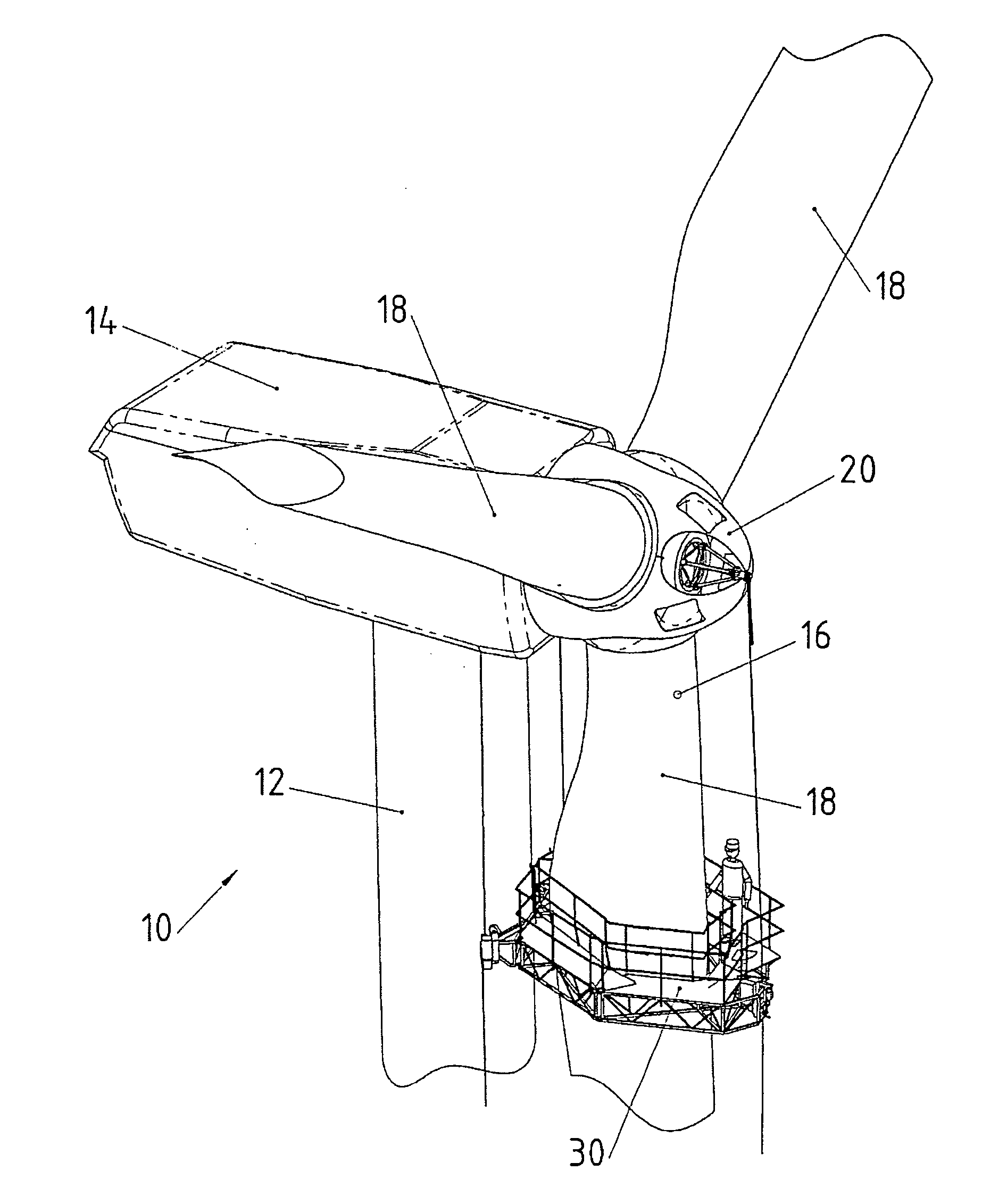
[0034] The wind turbine 10 shown in FIG. 1 comprises a tower 12, a horizontally swivelable nacelle 14 mounted on the top end of tower 12 and a rotor 16 which is rotatable about a horizontal axis and mounted inside nacelle 14. Rotor 16 comprises three rotor blades 18 attached to a common hub 20.

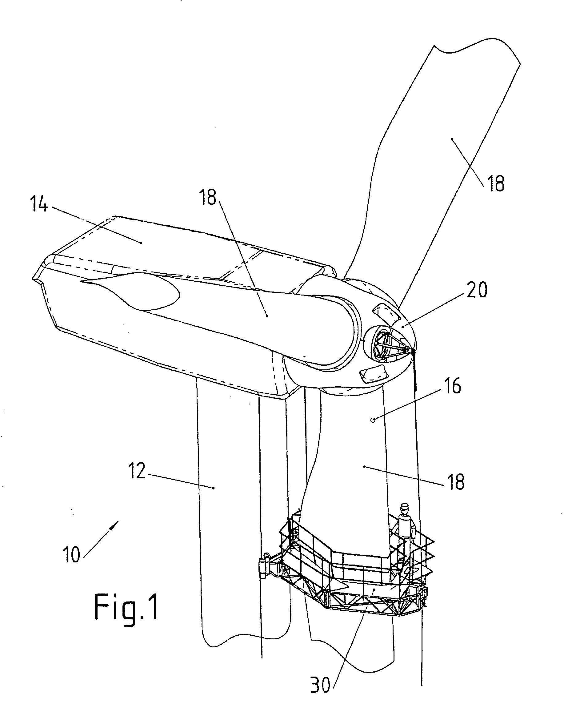
[0035] A maintenance platform 30 is suspended from nacelle 14 and hub 20 by means of three support cables 32. One of said support cables 32 is attached to hub 20 by means of a cable suspension member 34, while two additional support cables 32 are attached to nacelle 14. This is shown in greater detail in FIG. 2. The maintenance platform, support cables 32 and cable suspension member 34 together form a maintenance system.

[0036]FIG. 3 provides a separate view of maintenance platform 30. Maintenance platform 30 is comprised of four sub-platforms 36 swivably connected to each other by four swivel joints 38 to form a closed chain in the form of a four-bar linkage.

[0037]FIG. 3 also shows three ca...


PUM


Abstract

A maintenance platform for suspension on support cables, in particular for maintaining rotor blades of wind turbines, wherein the maintenance platform is formed by at least two sub-platforms defining a working plane, wherein said sub-platforms are swivably connected to each other by a swivel joint with a swivel axis substantially perpendicular to the working plane.

Description

TECHNICAL FIELD [0001] The invention relates to a maintenance platform for suspension on cables, in particular for maintaining wind turbine blades. BACKGROUND OF THE INVENTION [0002] In the Federal Republic of Germany, wind turbines are deemed by law to be building structures, the engineering design, erection and operation of which are supervised by the building permit offices of the separate states and by the locally competent building authorities. [0003] The competent authorities require above all that wind turbines, and especially their rotor blades and mechanical engineering components, be monitored at periodic intervals to maintain their operational safety. Irrespective of such requirements, regular maintenance and repair are essential for maximum availability of wind turbines. [0004] In the first years of wind power use, telescopic platforms or so-called aerial platforms, mounted on trucks, were used for inspecting, maintaining and repairing rotor blades. [0005] Owing to the r...

Claims


Application Information

Patent Timeline
Patent Type & Authority Applications(United States)
IPC IPC(8): E04G1/36E04G3/24E04G3/30E04G5/04F03D1/00
CPCE04G3/30E04G5/04E04G3/243Y02E10/721F03D1/003F03D80/50Y02E10/72
Inventor LEMBURG, CHRISTIANLEMBURG, JOHANNESSCHAFER, THOMASWEBER, CARSTEN
Owner AEROCONCEPT ING FUR LUFTFAHRTECHN & FASERVERBUNDTECH MBH
Why Eureka
Try Eureka