Switch

Inactive Publication Date: 2007-01-11
PANASONIC CORP
View PDF6 Cites 2 Cited by
  • Summary
  • Abstract
  • Description
  • Claims
  • Application Information

AI Technical Summary

Benefits of technology

[0013] The present invention aims at providing a switch capable of reliable operation with a simple structure to solve the conventional problems. The switch disclosed in the present invention comprises bosses protruding outward located below the supports extending downward to catch the side surfaces of the case. Even if the switches collide with

Problems solved by technology

However, when stored or transported in packed in bags or built into equipment, the aforementioned conventional

Method used


Image

  • Switch
  • Switch
  • Switch

Examples


Example

[0020] The preferred embodiment of this invention is described with reference to FIGS. 1 to 3. The similar configurations described in the background art have the same reference marks, and the detailed description thereof is omitted.

Preferred Embodiment

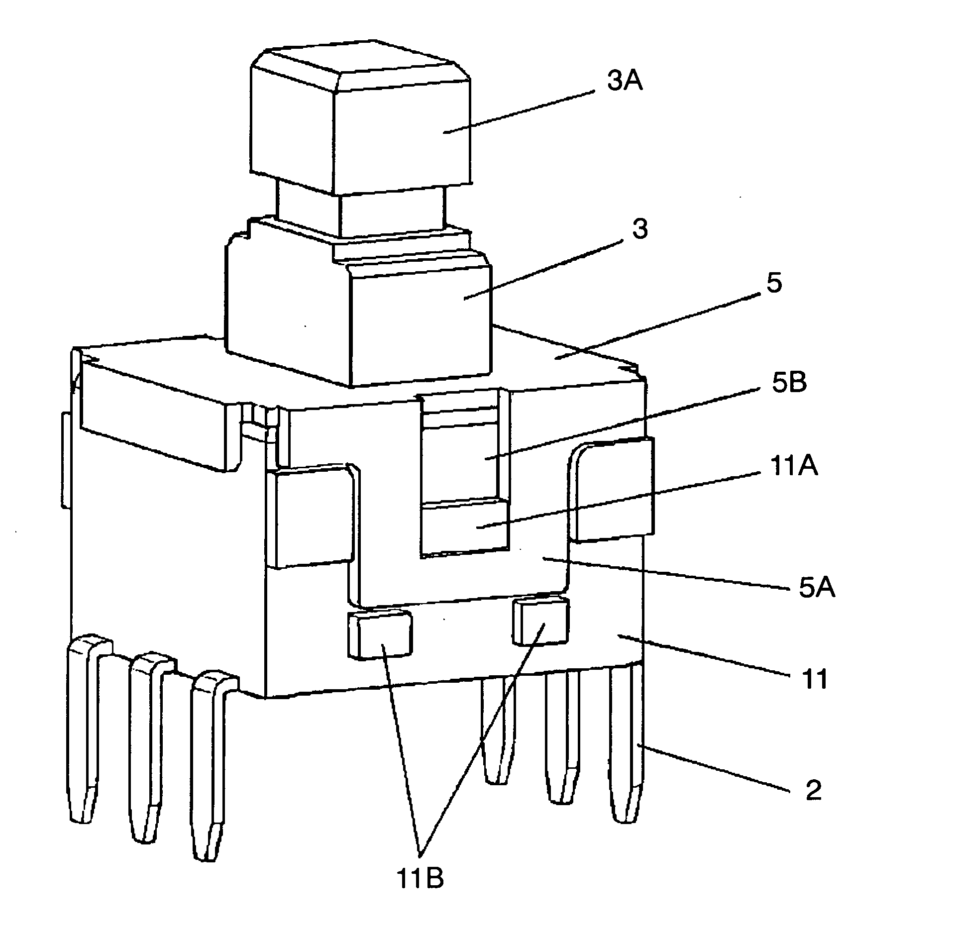
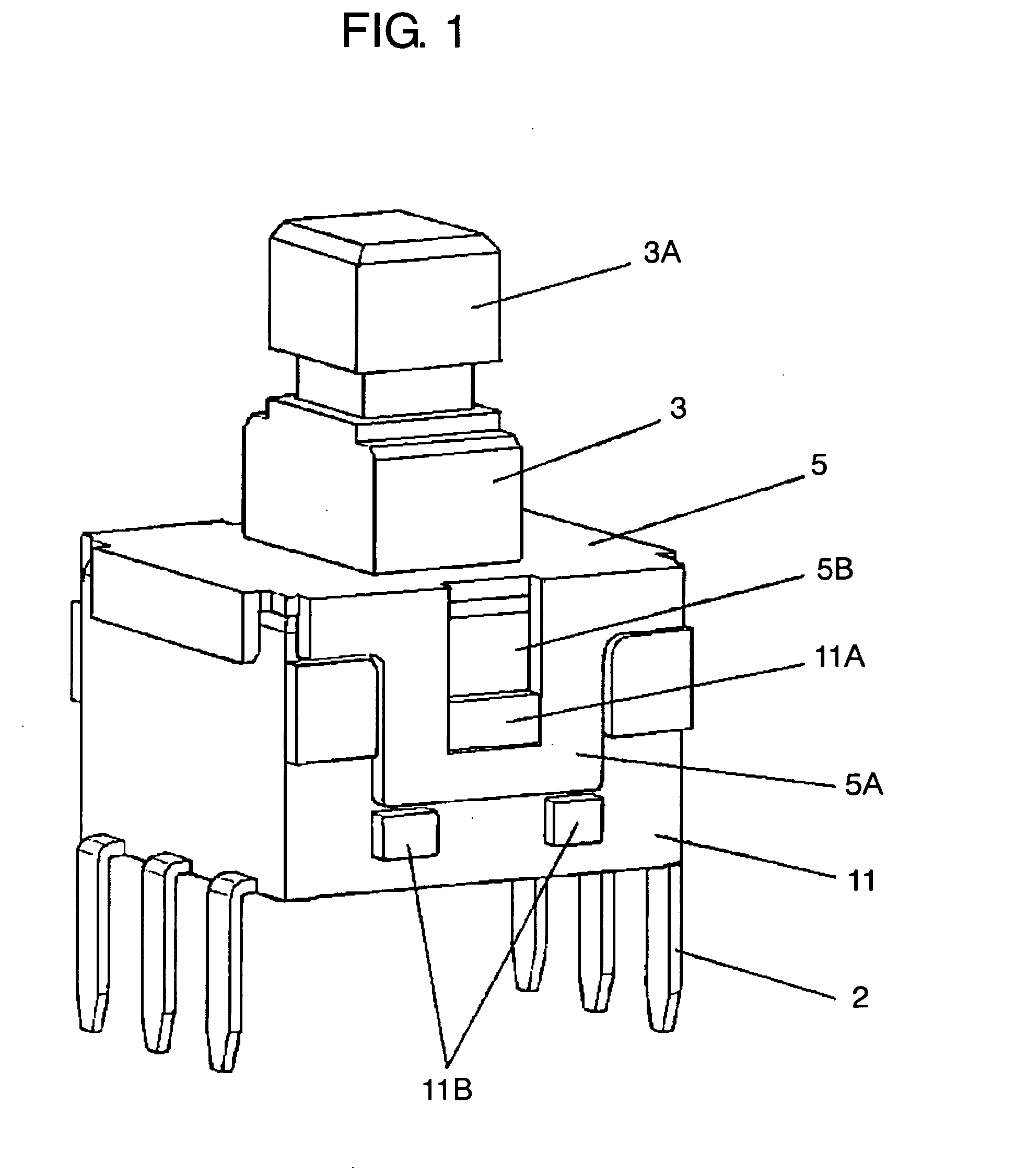
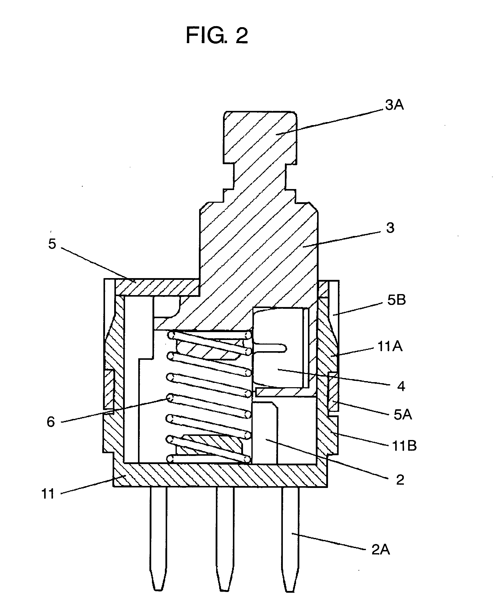
[0021]FIG. 1 shows a perspective view of the switch used in the preferred embodiment of the present invention, and FIG. 2 shows a cross-sectional view of the same. In FIGS. 1 and 2, open-topped box shaped case 1 is formed from an insulation resin such as polyphenylene sulfide, polybutylene terephthalate or the like. Fixed contact 2 is formed of thin conductive metal plate such as copper alloy or the like.

[0022] A plurality of fixed contacts 2 are implanted secured on internal surface of case 11, with terminal pins 2A protruding downward from the bottom surface of case 11.

[0023] Operating body 3 is formed from an insulation resin such as polyoxymethylene, polybutylene terephthalate or the like and is housed in case 11 movably verti...


PUM


Abstract

The switch disclosed comprises bosses, protruding outward from side surfaces of the case, located below the supports extending downward to catch the side surfaces of the case. Even if the switches collide with each other or with tools or the like occasionally, the bosses prevent the supports of cover from being put an outward force and thereby prevent the cover from coming off from the case. The structure can provide the switch with a reliable operationality.

Description

TECHNICAL FIELD [0001] The present invention relates to a switch used to operate electronic equipment. BACKGROUND ART [0002] With the advance in recent compact and low-profile design in various kinds of electronic equipment such as TV set, video recorder, air conditioner or the like, the switch used for the equipment is required to be also compact and low-profile and that can operate reliably. [0003] Such a conventional switch is described with reference to FIGS. 4 and 5. FIG. 4 shows a perspective view of the conventional switch and FIG. 5 shows a cross-sectional view of the same. In FIGS. 4 and 5, generally box shaped case 1 is formed from an insulation resin and is open-topped. Fixed contact 2 is formed of conductive thin metal plate. A plurality of fixed contacts 2 are implanted secured on internal surfaces of case 1, with terminal pins 2A protruding downward from the bottom surface of case 1. [0004] Operating body 3 is formed from an insulation resin and is housed in case 1 mov...

Claims


Application Information

Patent Timeline
IPC IPC(8): H01H21/00
CPCH01H13/04H01H9/02
Inventor KODOH, EIJI
Owner PANASONIC CORP
Why Eureka
Try Eureka