
Substrate for ink jet printing head, ink jet printing head, ink jet printing apparatus, and method of blowing fuse element of ink jet printing head

a technology of ink jet printing head and fuse element, which is applied in the direction of printing, inking apparatus, other printing apparatus, etc., can solve the problems of deteriorating productivity, difficult size and weight reduction, and disadvantage costwise, and achieves sufficient heating of fuse element, prolonging heating time, and high reliability

Active Publication Date: 2007-01-11
CANON KK
View PDF21 Cites 27 Cited by
  • Summary
  • Abstract
  • Description
  • Claims
  • Application Information

AI Technical Summary

Benefits of technology

The present invention provides a substrate for an ink jet printing head, an ink jet printing head, an ink jet printing apparatus, and a method of blowing a fuse element that can reliably store data. The substrate includes a current adjusting means that adjusts the electric current to flow in the fuse element for a predetermined duration after the maximum current has passed through it. The ink jet printing head ejects ink and can store data based on whether or not the fuse element has been blown. The ink jet printing apparatus includes a mounting portion for the ink jet printing head and means for reading data stored in the fuse element. The method involves applying an electric current to the fuse element and continuing to flow it for a predetermined duration after the maximum current has passed through it. This ensures reliable blowing of the fuse element and high reliability in storing data.

Problems solved by technology

The ink jet printing head disclosed in Japanese Patent Application Laid-open No. 3-126560 (1991), however, has the EEPROM mounted separately from the head substrate and thus its construction is complex, deteriorating a productivity and making a size and weight reduction difficult.
Another disadvantage is that although the existing ROM chip is useful when print data is large, it becomes a disadvantage costwise when the print data is small.
This method, however, is not suited for mass production because a melted material produced when the fuse element 410 is blown adheres to the printed circuit board and because the fuse element blowing process makes this method costly.
If, for example, the ink infiltrates into a portion where a fuse element was blown, that portion and electrodes may be corroded deteriorating reliability.

Method used


Image

  • Substrate for ink jet printing head, ink jet printing head, ink jet printing apparatus, and method of blowing fuse element of ink jet printing head
  • Substrate for ink jet printing head, ink jet printing head, ink jet printing apparatus, and method of blowing fuse element of ink jet printing head
  • Substrate for ink jet printing head, ink jet printing head, ink jet printing apparatus, and method of blowing fuse element of ink jet printing head

Examples


Embodiment Construction

[0042] Referring to the accompanying drawings, preferred embodiments of this invention will be described.

[0043] First, an example construction of an ink jet printing apparatus that can apply the present invention will be explained. The ink jet printing apparatus of this embodiment is of a serial scan type as shown in FIG. 8, and its control system is configured as shown in FIG. 9.

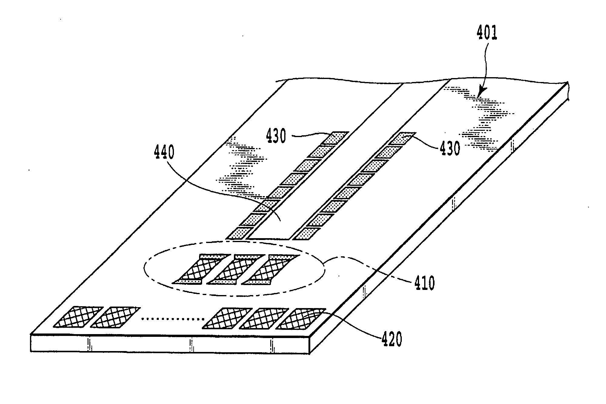
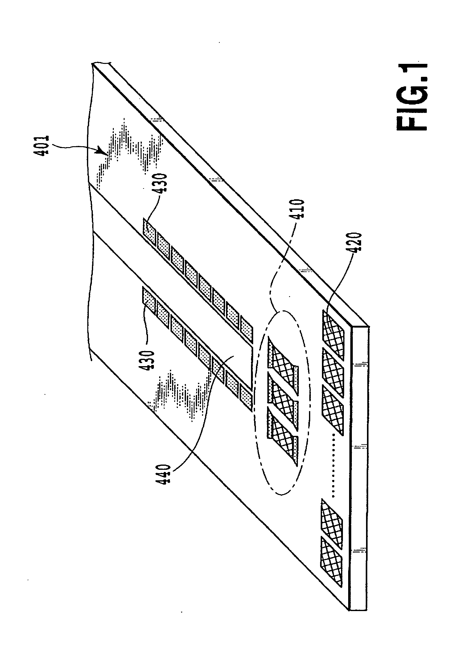
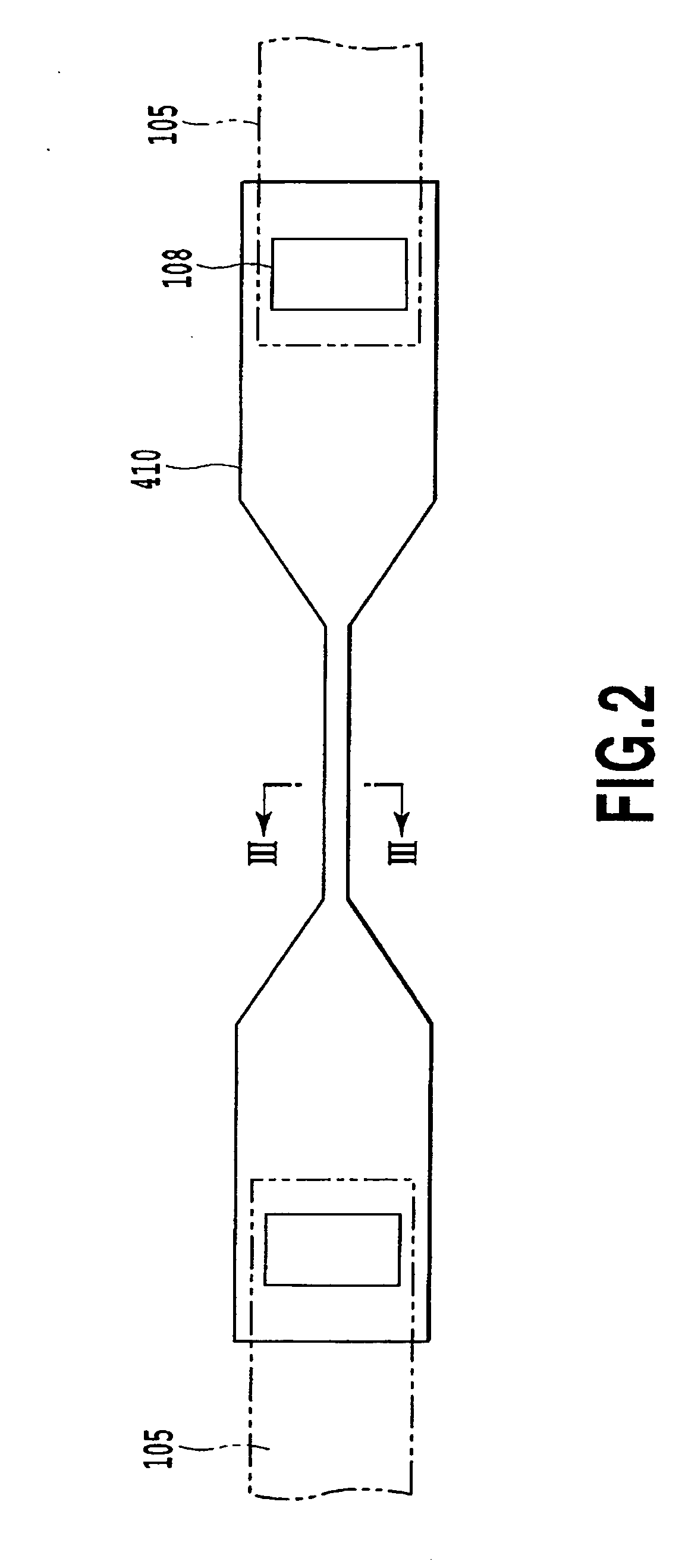
[0044] The ink jet printing apparatus 300 of this example, as shown in FIG. 8, prints an image by using an ink jet printing head 400. The printing head 400 incorporates a base 401 (see FIG. 1) which has formed in its surface heater elements 430, wires and fuse elements 410. The base 401 is also formed with electrode pads 420 for electrically connecting a head substrate including the base 401 with external terminals.

[0045] The printing head 400 is removably mounted on a carriage 303 of a head moving mechanism 302. The carriage 303 is supported on a guide shaft 304 so that it can be moved in a main scannin...


PUM


Abstract

The present invention reliably blows a fuse element to store with high reliability data that corresponds to whether or not the fuse element has been blown. For this purpose, a resistor element is provided in a circuit through which an electric current flows to blow the fuse element in the ink jet printing head. The resistor element adjusts the electric current so that, in the process of blowing the fuse element, the current continues to flow for a predetermined duration even after a maximum current has passed through the fuse element. The predetermined duration is longer than a period from a time point when the electric current rises to a time point it reaches the maximum current.

Description

BACKGROUND OF THE INVENTION [0001] 1. Field of the Invention [0002] The present invention relates to a substrate for an ink jet printing head with fuse element that can be blown by passing an electric current therethrough, an ink jet printing head with the substrate, an ink jet printing apparatus using the ink jet printing head, and a method of blowing the fuse element of the ink jet printing head. [0003] 2. Description of the Related Art [0004] A variety of types of printing apparatus, such as laser printers and ink jet printers, have been in use. An ink jet printer (ink jet printing apparatus) forms an image by ejecting ink droplets from a printing head. The ink ejection method includes an electrothermal conversion method (bubble jet system) that uses electrothermal transducers (heating elements). The ink jet printing head of the electrothermal conversion type holds a liquid ink in an ink holding unit comprising a nozzle, an ink supply path and an ink reservoir. The heating elemen...

Claims


Application Information

Patent Timeline
Patent Type & Authority Applications(United States)
IPC IPC(8): B41J2/05
CPCB41J2/04541B41J2202/17B41J2/0458B41J2/04565
Inventor HATSUI, TAKUYAOZAKI, TERUOSAITOYOKOYAMA, SAKAISHIBATA, KAZUAKIMATSUI, TAKAHIRO
Owner CANON KK
Learn More