
Image processing device, image processing method, and image processing program

a technology of image processing and image processing method, applied in the field of image processing device, image processing method, image processing program, can solve the problems of unpleasant noise, image quality, and appearance of output image, and achieve the effect of suppressing unpleasant noise and little scattering

Inactive Publication Date: 2007-01-11
SEIKO EPSON CORP
View PDF13 Cites 11 Cited by
  • Summary
  • Abstract
  • Description
  • Claims
  • Application Information

AI Technical Summary

Benefits of technology

[0011] In order to attain the above object, an image processing device of the present invention, which divides an input image into pixel groups having a plurality of pixels and performs quantization processing in units of the pixel groups, having a quantization unit which converts input image data into output image data having two or more grayscales, using the pixel groups the shapes of which are point-symmetric. Therefore, for example, if a dot is generated at the pixel of the center-of-gravity position of a pixel group, then even if there is a slight change in a uniform input grayscale distribution, the center-of-gravity position of the pixel group is positioned in proximity to the center of the dot generation pixel, so that there is no scattering in the pixel position of dot generation, and an output image is obtained in which unpleasant noise is suppressed.
[0013] Further, the image processing device of the present invention, wherein the pixel hold in common by the pixel groups is a pixel which is at an equal distance from the center of each of the pixel groups. Therefore, the number of pixels common to pixel groups can be made small, and increases in the amount of processing due to common pixels can be reduced.
[0015] Further, the image processing device of the present invention, wherein the quantization unit having a center-of-gravity position determination unit which determines the center-of-gravity position of the pixel groups from values obtained by multiplying the input image data for each of the pixels included in the pixel group by the commonality level, a positioning unit which positions the center of a multivalued dithering matrix, applied in units of the pixel groups, at the center-of-gravity position of the pixel group, and an output unit which compares the multivalued dithering matrix with the input image data for each of the pixels included in the pixel group, to obtain the output image data. Therefore, the center-of-gravity position is determined using the value obtained by for example multiplying the commonality level by the input image data for each pixel, so that the influence on the accurate center-of-gravity position of common pixels due to processing for a plurality of pixel groups can be reduced.
[0019] Further, in order to attain the above objects, an image processing device of the present invention, which divides an input image into pixel groups having a plurality of pixels and performs quantization processing in units of the pixel groups, having a quantization unit, which converts input image data into output image data having two or more grayscales, using the pixel groups in which the center position of the pixel group and the center position of any pixel included in the pixel groups coincide. Therefore, for example, if a dot is generated at the pixel of a pixel group at which the center-of-gravity position exists, then even if the uniform input grayscale distribution changes slightly, the center-of-gravity position of the pixel group is positioned in proximity to the center of the pixel at which the dot was generated, so that there is little scattering in the position of the pixel of dot generation, and an output image is obtained in which unpleasant noise is suppressed.

Problems solved by technology

However, in multivalued dithering methods, distribution of thresholds may for example cause the breaking of fine lines when there are fine lines in the input image, or may cause the occurrence of “jaggies” at edge portions of the input image, so that an image which is not true to the input image is output, and there are problems with image quality.
This scattering in dot positions results in unpleasant noise and appears in the output image.

Method used


Image

  • Image processing device, image processing method, and image processing program
  • Image processing device, image processing method, and image processing program
  • Image processing device, image processing method, and image processing program

Examples


first embodiment

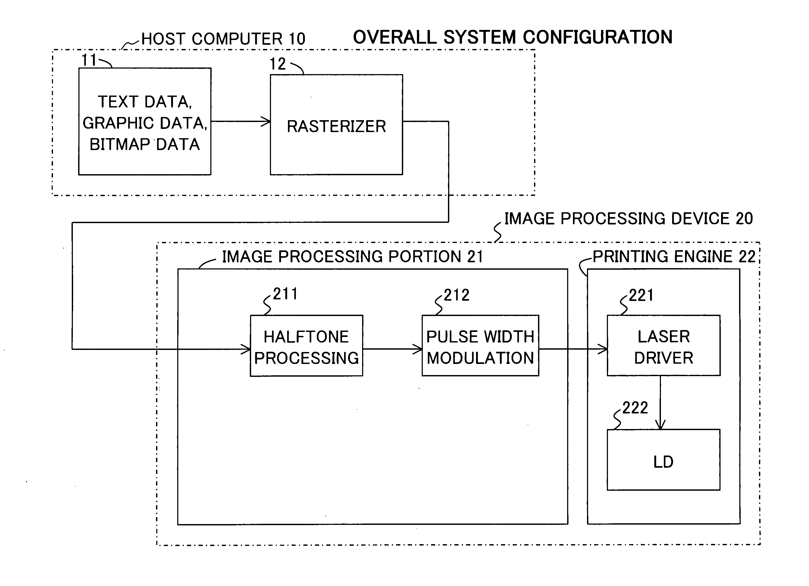
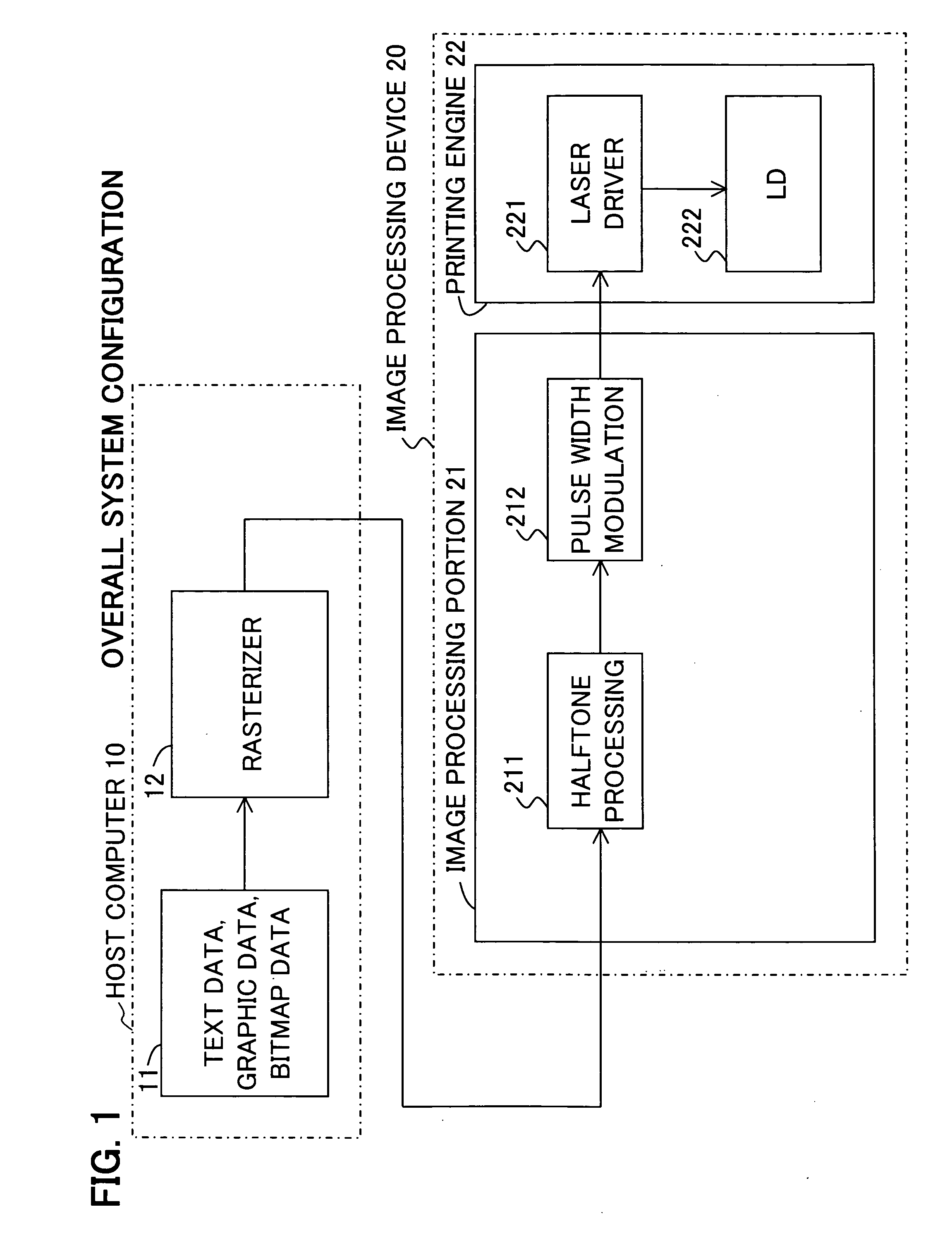
[0042] Below, preferred embodiments for implementation of the invention are explained, referring to the drawings. FIG. 1 shows the overall configuration of a system to which this invention is applied. This system as a whole comprises a host computer 10 and an image processing device 20.

[0043] The host computer 10 comprises an application portion 11 and a rasterizing portion 12.

[0044] The application portion 11 generates text data, graphical data, or other data for printing by means of a word processor, graphics tool, or other application program. The rasterizer portion 12 converts each pixel (or dot) of the data for printing into 8-bit input image data, and outputs the result to the image processing device 20. Hence the input image data has, for each pixel, grayscale values ranging from “0” to “255”.

[0045] The image processing device 20 comprises an image processing portion 21 and a printing engine 22. The image processing portion 21 comprises a halftone processing portion 211 an...

second embodiment

[0077] In the first embodiment, a case of input of uniform grayscale data was explained. In this second embodiment, an example in which grayscale values are concentrated on the left side of the cell 200 is explained. This example appears in (A) of FIG. 11. The cell 200 indicated by the bold line is taken to be the cell for processing at a certain time. Input data in the cell 200 is distributed as shown in (B) of FIG. 11.

[0078] First, the CPU 24 multiplies input grayscale values by contribution factors (S11; see (C) of FIG. 11).

[0079] Next, the CPU 24 computes the sum of grayscale values using the multiplied values (computes the ideal grayscale value) and computes the center-of-gravity position 110 (S12; see (A) in FIG. 12).

[0080] Next, the CPU 24 determines the order of processing, starting from pixels closer to the center-of-gravity pixel (S13; see (B) in FIG. 12).

[0081] Next, the CPU 24 shifts the center of the index matrix (S14). In the case of this example, the center-of-gra...

third embodiment

[0087] This third embodiment is an example of a case in which grayscale values exist only in the common pixels 210 of cells 200. An example of input data appears in (A) of FIG. 14. Similarly to the above, a case is explained in which the cell 200 indicated by the bold line is to be processed at a certain time.

[0088] When the contribution factor is multiplied by the input grayscale value for each pixel (S11), the data shown in (C) of FIG. 14 is obtained. Upon using values multiplied by contribution factors to compute the sum of grayscale values and the center-of-gravity position 110 (S12), (A) in FIG. 15 is obtained. The center-of-gravity position 110 is positioned at a common pixel 210 two pixels to the left of the center of the cell 200.

[0089] The processing order is determined (S13; see (B) of FIG. 15), the index matrix is shifted by (−2,0) (S14; see (C) of FIG. 15), and output values are allocated in the order thus determined.

[0090] That is, the output value “255” correspondin...


PUM


Abstract

An image processing device, image processing method, and image processing program are provided, to obtain an output image in which the occurrence of unpleasant noise is suppressed. An image processing device, which divides an input image into pixel groups having a plurality of pixels and performs quantization processing in units of these pixel groups, has quantization unit which uses pixel groups, the shapes of which are point-symmetric, to convert input image data into output image data having two or more grayscales.

Description

CROSS-REFERENCE TO RELATED APPLICATIONS [0001] This application is based upon and claims the benefit of priority from the prior Japanese Patent Application No. 2005-196256, filed on Jul. 5, 2005, the entire contents of which are incorporated herein by reference. BACKGROUND OF THE INVENTION [0002] 1. Field of the Invention [0003] This invention relates to an image processing device, an image processing method, and an image processing program. More specifically, the invention relates to an image processing device and similar which performs quantization processing using cells the shapes of which have been rendered symmetrical. [0004] 2. Description of the Related Art [0005] In the prior art, printers and other image processing devices use halftone processing of input image data having multivalued grayscale values for each pixel to convert the data into output image data with a smaller number of grayscales (for example, with two data values), to perform printing onto printing paper. [00...

Claims


Application Information

Patent Timeline
IPC IPC(8): G06K15/00
CPCH04N1/4055
Inventor KARITO, NOBUHIRO
Owner SEIKO EPSON CORP
Learn More