Apparatus for foaming a slurry

a technology of apparatus and foaming slurry, which is applied in the direction of clay preparation apparatus, cement mixing apparatus, mixers, etc., can solve the problems of difficulty in controlling the size of the forming pores, unable to foam slurries insufficiently with conventional agitators, and unable to control the pore distribution of foaming slurry, etc., to achieve simple construction, increase the foaming of the slurry, reduce the effect of air quantity

Inactive Publication Date: 2007-01-11
KDM ENG
View PDF8 Cites 7 Cited by
  • Summary
  • Abstract
  • Description
  • Claims
  • Application Information

AI Technical Summary

Benefits of technology

[0006] By providing agitating units with agitator rods which are parallel to their rotational axis it is possible to advantageously introduce air into the slurry. The diameter of the agitator rods determines the size of the introduced air bubbles and thus the later pores. The later pore size can be predetermined by the diameter of the employed agitator rods, with thinner agitator rods leading to finer air bubbles and larger agitator rods leading to larger air bubbles. The rotational speed of the agitator rods of the individual agitating units has a direct influence on the rate of the air introduced into the slurry and thus on the share of pores. Since the agitating units of the agitator are driven in opposite directions, a conveying effect on the slurry to be foamed occurs between adjacent agitating units. The slurry is sucked in on the side of rods of adjacent rotors rotating into the interstitial region and is ejected on the opposite side of the interstitial region. This conveying effect ensures in combination with the relative rotation between the entire agitator and the vessel an even inclusion of the entire slurry mass and thus an even distribution of pores over the foamed slurry. When making a respective choice of the rotational speed of the agitator rods, air can be introduced in a quantity which makes up at least 80 percent by volume of the foamed slurry even in the case of slurries whose shares of solids have a higher density than water; this occurs under an even distribution of the air bubbles whose size depends substantially on the diameter of the employed agitator rods. The foam structure of the foamed slurry is surprisingly sufficiently stable until the setting of the hydraulic binding medium within the slurry prevents a collapse of the foam, namely under the usual ambient conditions without the addition of any additional thermal energy, which may be supplied in any case however to accelerate the setting. In order to enable driving the rotors of the individual agitating units in an alternating manner in opposite directions, the rotors can comprise drive shafts which are operatively connected at least in groups by way of mutually combing gearwheels. The mutually combing gearwheels of adjacent rotors ensure the opposite direction of rotation of adjacent agitating units. The fact that the mutual distance of the agitating units cooperating in pairs is preferably chosen in a uniform way benefits the drive of the rotors by mutually engaging gearwheels.
[0007] In order to provide simple constructional conditions, the retainers for the agitator rods can sit on the drive shafts of the agitating units. The agitator rods of the agitating units enclose the respective drive shaft in at least one concentric pitch circle. If the agitator rods are arranged in two or more pitch circles then it is recommended to mutually offset the agitator rods of the individual pitch circles to form a gap relative to the agitator rods of adjacent pitch circles. This allows an even introduction of the air into the slurry in combination with favorable conveying conditions for the slurry.
[0008] As a result of the conveying effect of the agitating units cooperating in pairs on the slurry to be foamed, congestion effects can occur in the intake region of two adjacent agitating units, which congestion effects obstruct the even advance of the slurry between adjacent agitating units. To ensure that such congestion effects cannot have a disadvantageous effect on the air introduction into the slurry, the relative direction of rotation between the vessel and the agitator can be reversed, so that in the case of a repeated reversal of the direction of rotation of the vessel any congestion regions in the intake region between two agitating units are dissolved when an opposite conveying component acts upon the slurry as a result of the direction of rotation of the vessel contrary to the intake direction. In contrast to a reversal of the direction of rotation of the agitating units, a reversal of the movement of the relative rotation between the vessel and the agitator does not disturb the continued even introduction of air into the slurry.
[0009] Since the rate of air introduction changes with the degree of foaming of the slurry at the same rotational speed of the agitator rods, the introduction of air can be controlled depending on the degree of foaming by the rotational speed of the agitator rods, so that the introduced air quantity can be increased, reduced or kept constant with increasing foaming of the slurry depending on the respective requirements.

Problems solved by technology

The disadvantageous effect in this known production of such porous building materials and aggregates is, apart from the comparatively high production effort, that the size of the forming pores can hardly be controlled and it is only possible to take an influence on the pore distribution within the foaming slurry with difficulty.
Tests to avoid these difficulties by mechanical foaming of the slurry by adding a foaming agent such as ionogenic tensides have shown such slurries can only be foamed insufficiently with conventional agitators.

Method used


Image

  • Apparatus for foaming a slurry
  • Apparatus for foaming a slurry
  • Apparatus for foaming a slurry

Examples


Embodiment Construction

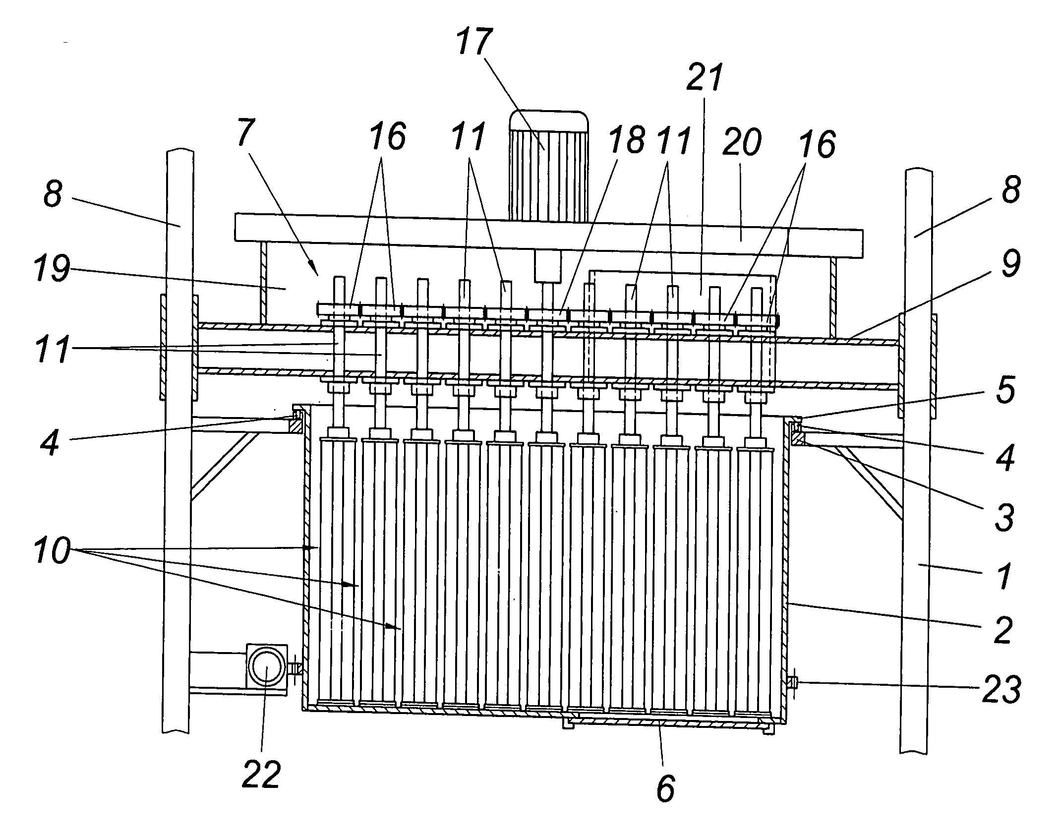
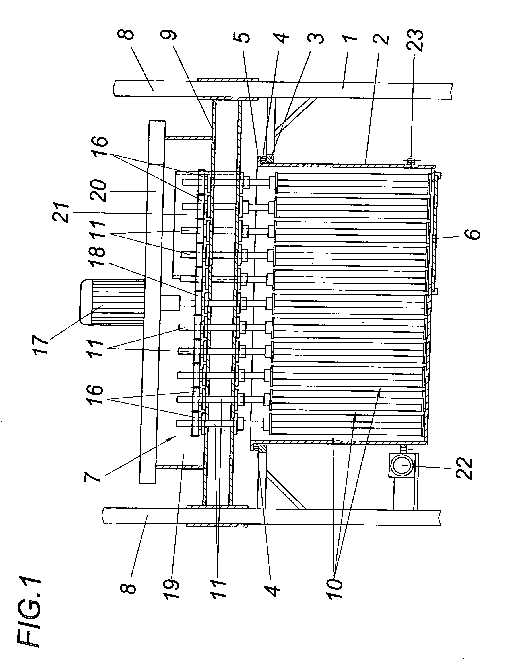
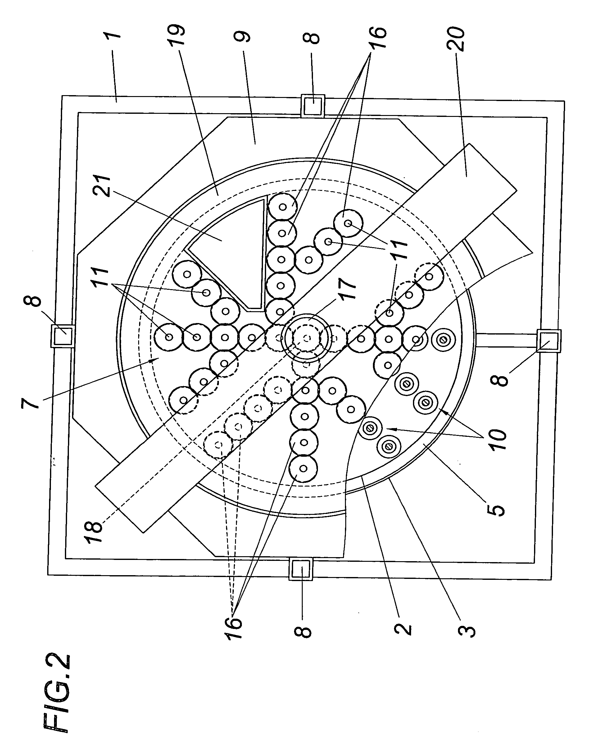
[0015] The illustrated apparatus for foaming a slurry comprises a frame 1 in which a cylindrical vessel 2 is rotatably held about the vessel axis for receiving the slurry to be foamed. For this purpose the frame 1 forms a carrying ring 3 into which the vessel 2 is hooked. Track rollers 4 are provided for supporting the vessel 2 on the carrying ring 3. The vessel 2 rests on the same via a boundary flange 5. A device 6 for discharging the foamed slurry in the form of a discharge slide is provided in the floor of the vessel 2.

[0016] An agitator 7 is used for foaming the slurry, which agitator is held in a carriage 9 being vertically adjustable on guide pillars 8 and consists of a plurality of agitating units 10. Said agitating units 10 form rotors which are parallel to the vessel axis and which each consists of a drive shaft 11 according to FIGS. 3 and 4 on which disk-like retainers 12 and 13, between which the axially parallel agitator rods 14 are arranged. Said agitator rods 14 whic...


PUM

PropertyMeasurementUnit
grain sizeaaaaaaaaaa
diameteraaaaaaaaaa
diameteraaaaaaaaaa

Abstract

An apparatus is described for foaming a slurry made of sand, water and a hydraulic binding medium by adding a foaming agent with a cylindrical vessel (2) for receiving the slurry and an agitator (7) revolving relative to the vessel about the vessel axis. In order to provide simple constructional conditions it is proposed that the agitator (7) comprises agitating units (10) distributed over the cross section of the vessel, which agitating units each consist of a rotor parallel to the vessel axis with agitator rods (14) between retainers (12, 13) on the face side, which rods are distributed over the circumference, are parallel to the axis and can be driven in an alternating manner in opposite directions.

Description

FIELD OF THE INVENTION [0001] The invention relates to an apparatus for foaming a slurry made of sand, water and a hydraulic binding medium by adding a foaming agent with a cylindrical vessel for receiving the slurry and an agitator revolving relative to the vessel about the vessel axis. DESCRIPTION OF THE PRIOR ART [0002] In the production of insulating materials and aggregates for the construction industry from sands bound with hydraulic binding mediums, e.g. quartz sand or sand-lime, a slurry is formed from the sands, the hydraulic binding agent and the water, which is foamed prior to hardening. It is known for this purpose to add an aluminum powder as an expanding agent to the slurry, which powder splits the water into hydrogen and oxygen and thus provides propellants leading to the formation of pores in the slurry. The hardening of the foamed slurry occurs under the influence of heat and pressure in autoclaves. The disadvantageous effect in this known production of such porous ...

Claims


Application Information

Patent Timeline
Patent Type & Authority Applications(United States)
IPC IPC(8): B01F7/32B01F27/96B28C5/32B28C5/38
CPCB01F3/04453B01F7/00975B01F7/1665B28C5/383B01F15/00454B01F2015/00636B28C5/325B01F7/32B01F23/2351B01F27/2322B01F27/85B01F27/96B01F35/3231B01F35/332
Inventor KRANZINGER, NORBERT
Owner KDM ENG
Why Eureka
Try Eureka