
BTE/CIC auditory device and modular connector system therefor

a technology of auditory devices and connectors, applied in the field of auditory devices, can solve the problems of cosmetically undesirable devices, bulky and uncomfortable earpiece auditory devices, and users may not want others to know they are using earpiece auditory devices, etc., and achieve the effect of reducing feedback

Inactive Publication Date: 2007-01-11
HEAR WEAR TECH
View PDF99 Cites 49 Cited by
  • Summary
  • Abstract
  • Description
  • Claims
  • Application Information

AI Technical Summary

Benefits of technology

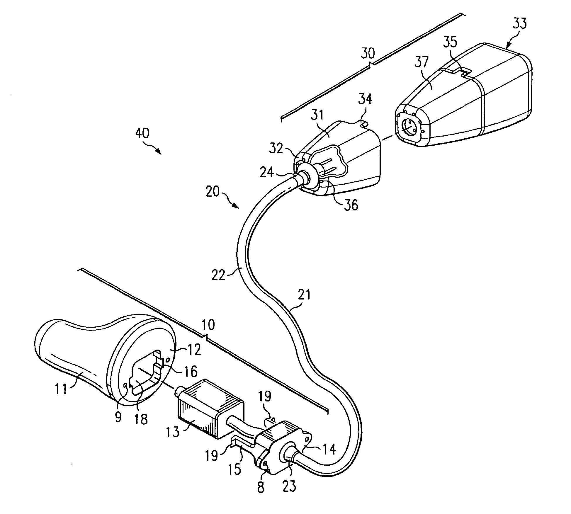
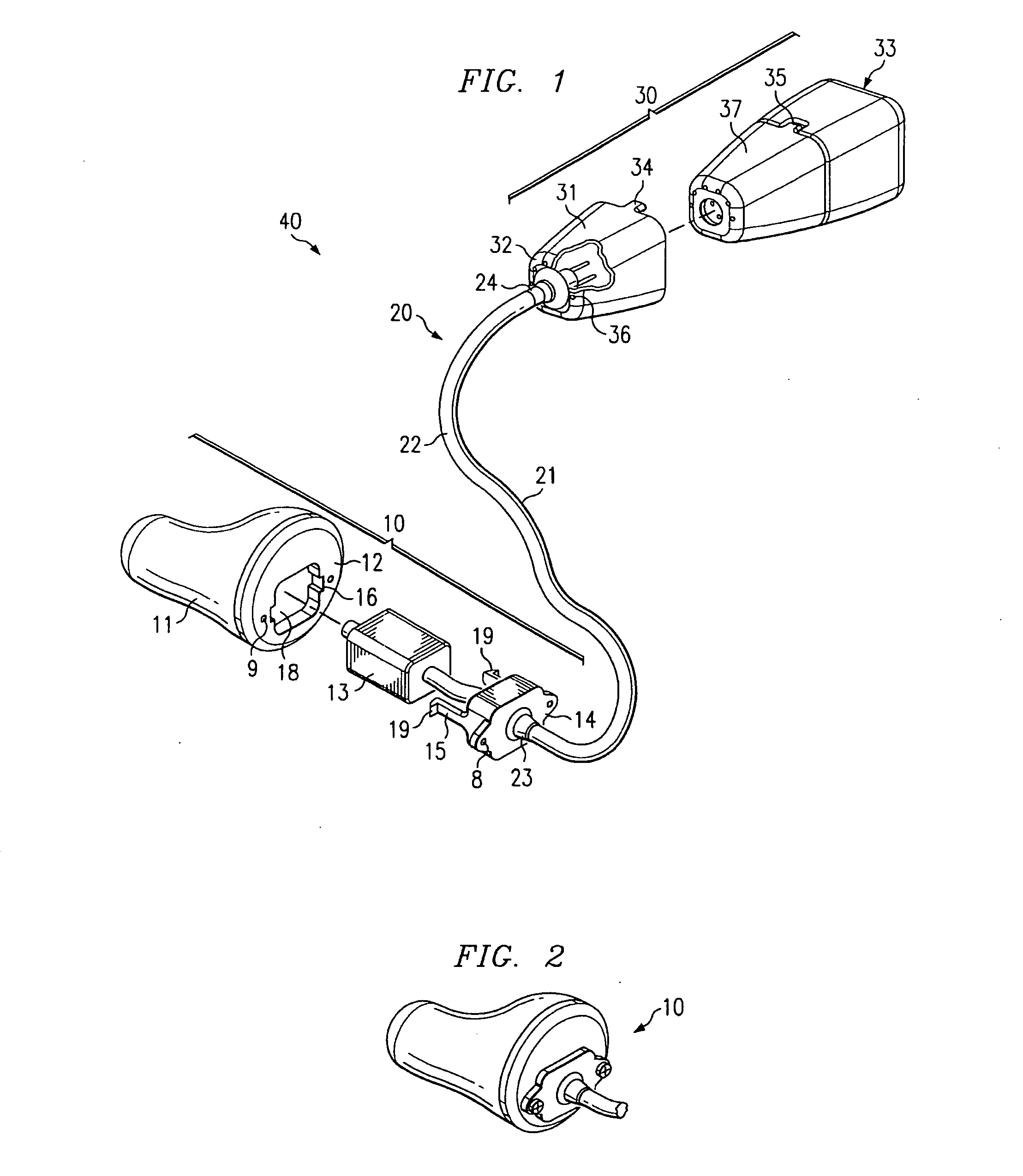
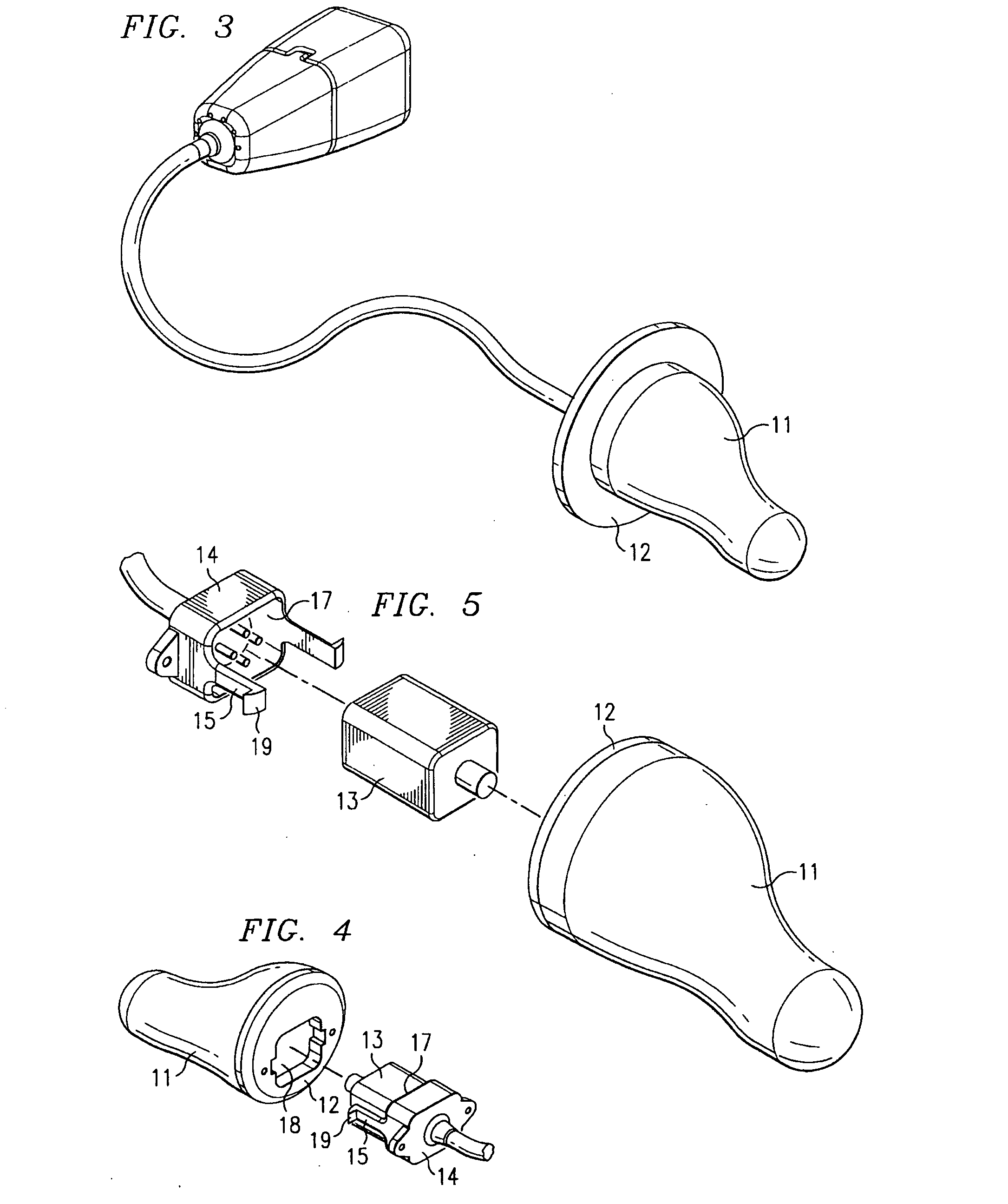
"The present invention is an earpiece auditory device that includes a behind-the-ear component and a completely-in-canal component. The behind-the-ear component has processing circuitry and is designed to fit behind the user's ear. The completely-in-canal component is designed to fit into the user's ear canal and can include a universal fit ear mold or a custom fit ear mold. The ear mold can be detachably interconnected with a speaker module or permanently encapsulated within the ear mold. The earpiece auditory device also includes a connector that connects the behind-the-ear and completely-in-canal components. The technical effects of the invention include ease of assembly, disassembly, and reassembly, as well as reducing feedback and occlusion effect."

Problems solved by technology

Conventional earpiece auditory devices (e.g., earphones, headphones, headsets, monitors, IFB devices, hearing aids, earplugs, etc.) are often bulky and uncomfortable for a user to wear.
In addition, typically, these devices are cosmetically undesirable.
However, in some circumstances, users may not want others to know they are using an earpiece auditory device.
As another example, news anchors using IFB devices may not want the device to be seen on camera.
Moreover, use of a bulky and noticeable earpiece auditory device may potentially have more serious consequences.
For example, a bulky, noticeable earpiece auditory device may put plain-clothed security personnel at risk of being discovered.
However such devices, although possibly reducing some of the conspicuousness of the device, create their own set of problems.
For example, placing an auditory device within the outer portion of an ear canal of a user may cause the user to experience the occlusion effect, which is a plugged sensation that results when the ear canal is blocked and air conduction is impeded by the introduction of at least a portion of an earpiece auditory device into the outer portion of the ear canal.
However, unfortunately, when an earpiece auditory device of sufficient size is placed in the outer portion of the ear canal, at least a portion of this energy is trapped in the user's ear, thereby causing the above described plugged sensation.
In addition, certain of the existing earpiece auditory devices (of both the behind the ear and within the ear or ear canal varieties) experience feedback problems.
One notably undesirable consequence of this mechanical coupling is electroacoustic feedback.
The above discussed feedback problems increase as the gain of the auditory device increases.
As a result, the gain of such auditory devices are limited by the electroacoustic feedback.
While such a design may result in reduced electroacoustic feedback, it would be commercially unacceptable.
However, as a result of such fixed couplings, assembly of the devices and / or replacement of defective or expired parts is normally costly, time-consuming, and / or burdensome.
Although there are some advantages to this procedure (e.g., providing a desired fit to a particular user), one notable disadvantage to customizing these devices in this manner, at least to a manufacturer, is that such devices can then not be mass produced.
Furthermore, another disadvantage of this customizing of portions of earpiece auditory devices to a particular customer's ear shape is that if, upon delivery to the user, it is discovered that the fit of the auditory device is deficient in some manner, as was the case with replacing defective or expired parts, replacement of the ill-fitting earpiece is costly, time-consuming, and burdensome.

Method used


Image

  • BTE/CIC auditory device and modular connector system therefor
  • BTE/CIC auditory device and modular connector system therefor
  • BTE/CIC auditory device and modular connector system therefor

Examples


Embodiment Construction

[0040] The inventors of commonly assigned U.S. Pat. No. 5,606,621 issued Feb. 27, 1997, entitled “HYBRID BEHIND-THE-EAR AND COMPLETELY-IN-CANAL HEARING AID,” the disclosure of which is hereby incorporated herein by reference, developed a hybrid behind-the-ear (“BTE”) / completely-in-canal (CIC) hearing aid. In one embodiment, the hearing aid of the '621 application has two components: a BTE component and a CIC component. Preferably, these components are mechanically isolated from each other. The BTE component, which is worn behind the ear, preferably includes at least a microphone. In one embodiment, the BTE also includes a power source, and sound processing circuitry (e.g., amplifiers, compressors, filters, etc.). Meanwhile, the CIC component is preferably shaped to fit into the ear canal of the patient in such a manner as to touch the bony portion of the ear canal. In one embodiment, the CIC component contains a speaker, the speaker preferably being operatively connected to the soun...


PUM

PropertyMeasurementUnit
sound attenuationaaaaaaaaaa
lengthaaaaaaaaaa
dimensionsaaaaaaaaaa

Abstract

An earpiece auditory device is described which includes a behind-the-ear component shaped to fit behind the ear of a user. The behind-the-ear component can also have at least one microphone and processing circuitry, where the processing circuitry is used to processes audio signal from the microphone. The device also includes a speaker sized to fit in the ear canal of a user, and an ear mold holding the speaker in place. The ear mold can also be position to touch the bony portion of the ear canal and provide sound attenuation in the ear canal. A connector physically and electrically connects the behind-the-ear component to the speaker. The connector is capable of being used to insert and remove the speaker and ear mold from the ear canal of the user.

Description

CROSS-REFERENCE TO RELATED APPLICATIONS [0001] This Application is a Continuation claiming priority benefit of co-pending and commonly assigned U.S. patent application Ser. No. 10 / 238,829 entitled “A BTE / CIC AUDITORY DEVICE AND MODULAR CONNECTOR SYSTEM THEREFOR,” filed Sep. 10, 2002, which is a Continuation-in-Part of application Ser. No. 09 / 927,891 entitled “A BTE / CIC AUDITORY DEVICE AND MODULAR CONNECTOR SYSTEM THEREFOR,” filed Aug. 10, 2001, the disclosure of which is hereby incorporated herein by reference.TECHNICAL FIELD [0002] This invention relates generally to auditory devices, and particularly to a hybrid behind-the-ear (BTE) / completely-in-canal (CIC) auditory device and a modular connector system therefor. BACKGROUND OF THE INVENTION [0003] Conventional earpiece auditory devices (e.g., earphones, headphones, headsets, monitors, IFB devices, hearing aids, earplugs, etc.) are often bulky and uncomfortable for a user to wear. In addition, typically, these devices are cosmetic...

Claims


Application Information

Patent Timeline
Patent Type & Authority Applications(United States)
IPC IPC(8): H04R25/00
CPCB29C67/0051H04R1/1016H04R1/1058H04R25/554H04R2225/63H04R25/604H04R25/652H04R25/656H04R25/60H04R2225/0213B33Y80/00B33Y70/00H04R2225/57H04R25/607H04R25/609
Inventor FEELEY, JIMFEELEY, MIKE
Owner HEAR WEAR TECH
Learn More