
Electroimpedance tomograph with common-mode signal suppression

a tomograph and common-mode technology, applied in the field of tomographs with a plurality of electrodes, can solve the problems of limiting the measurement technique, requiring sufficient representation, and requiring simple increase in measuring current,

Active Publication Date: 2007-01-11
DRAGERWERK AG
View PDF5 Cites 70 Cited by
  • Summary
  • Abstract
  • Description
  • Claims
  • Application Information

AI Technical Summary

Benefits of technology

[0013] The object of the present invention is therefore to provide an electroimpedance tomograph in which interferences with the measured signals due to common-mode signals are further suppressed.
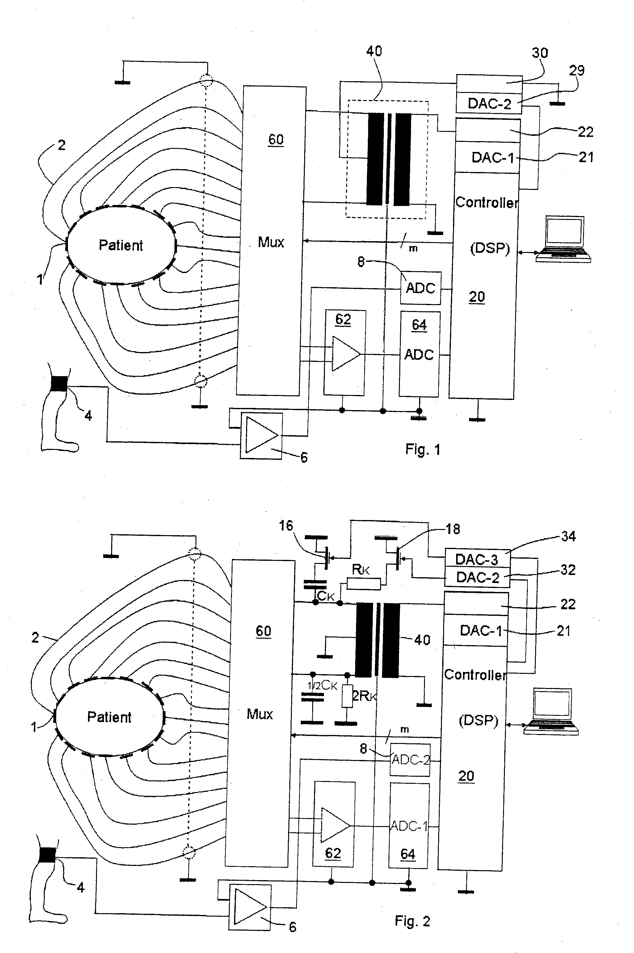
[0015] According to another aspect of the invention, an ectroimpedance tomograph is with a plurality of electrodes, which can be placed on the body of a patient and are connected to a control and evaluating unit. The control and evaluating unit cooperates with the selector switch such that two electrodes each are supplied with an alternating current from an AC power source. The detected analog voltage signals of the other electrodes are processed in order to reconstruct therefrom the impedance distribution of the body in the plane of the electrodes. A symmetrical AC power source is used to reduce common-mode signals. An analog control loop circuit with a differential amplifier is present, where one input of the differential amplifier is connected to the ground and the other input thereof is connected to the output of a common-mode signal measuring electrode, which supplies the common-mode signal of the alternating current on the body. The output of the differential amplifier is connected to a center tap of the symmetrical AC power source in order to detune this power source such that the common-mode signal on the body is minimized.
[0017] In a preferred embodiment, the control and evaluating unit is connected to a compensation AC power source, whose output is superimposed to the symmetrical AC power source. The control and evaluating unit controls the compensation AC power source according to the measured common-mode signal in terms of amplitude and phase such that the symmetry of the symmetrical AC power source is detuned such as to minimize the common-mode signal on the body.
[0018] In another preferred embodiment, passive compensation members are connected to a first output of the symmetrical AC power source, one compensating member being connected, in particular, via a resistor and a control transistor and one compensation member being connected via a capacitor and a control transistor, e.g., to the ground. The control and evaluating unit is set up to control the compensation members via their control transistors according to the measured common-mode signal such that the symmetry of the AC power source is detuned such as to minimize the common-mode signal on the body. The other output of the symmetrical AC power source is preferably detuned in advance in the opposite sense, so that an adjusting point can be obtained with certainty according to value and phase at the first output by the active reaction of the controllable compensation members in order to minimize the common-mode signal on the body.

Problems solved by technology

A measuring technical problem in electroimpedance tomography is that the useful signal used to calculate the graphic representation must be sufficiently larger than the particular interferences.
The simple increase in the measuring current has limits, because the currents that are permissible according to the standards are limited (in a frequency-dependent manner).
One of the interferences occurring in terms of measuring technique during impedance tomography is the ultimately unavoidably occurring residual asymmetry of the alternating current feed on the body, which also occurs when a symmetrical AC power source is used, which is due to the differences in the routing of the cables to the different electrodes, different contact resistances, etc.
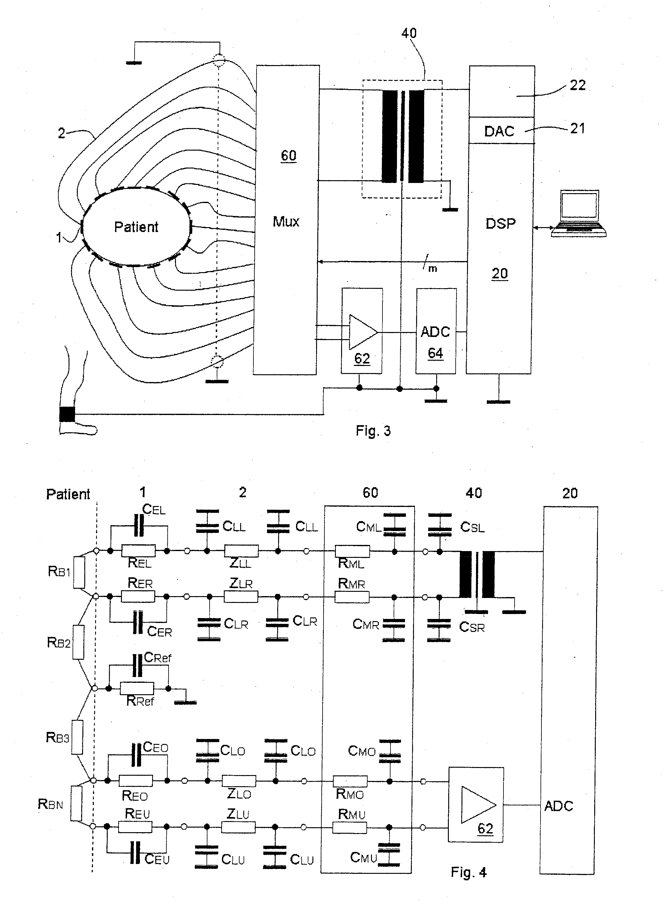
Moreover, they are complex, i.e., they are composed mainly of the transition resistances REL and RER and the transition capacitances CEL and CER.
The size of the possible reference ground electrodes and their ability to be handled are limited and, beginning from a certain size, they generate movement artifacts, which originate from the changes in the transition impedance that are generated during the movement of the patient.
Therefore, this measure only has limited effectiveness.

Method used


Image

  • Electroimpedance tomograph with common-mode signal suppression
  • Electroimpedance tomograph with common-mode signal suppression
  • Electroimpedance tomograph with common-mode signal suppression

Examples


Embodiment Construction

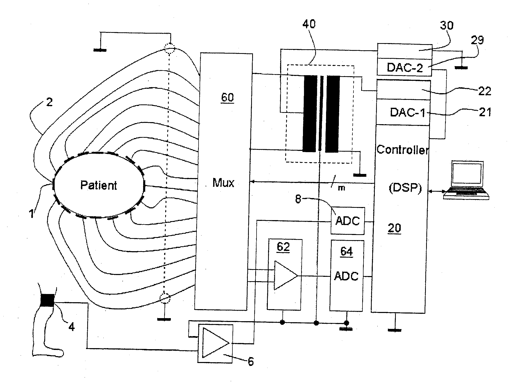
[0029] Referring to the drawings in particular, the electroimpedance tomograph shown in FIG. 1 has a control and evaluating unit 20, which is connected via a digital-analog converter 21 to an AC power source 22 for controlling same. The alternating current of the power source 22 is galvanically separated from the selector switch 60 via an isolation transformer or transformer 40. The selector switch or multiplexer 60 applies the AC signal with the cable 2 to two electrodes 1 each (only one of a total of 16 electrodes is provided with a reference number). The other electrodes are then used consecutively as measuring electrodes in pairs. The voltage signals of the measuring electrodes are sent to the control and evaluating unit 20 via the multiplexer 60 and a differential amplifier 62 and an analog-digital converter 64. The feeding electrode pairs 1 rotate now around the patient's body, controlled by the control and evaluating unit 20 and the multiplexer 60, and an electroimpedance tom...


PUM


Abstract

An electroimpedance tomograph with a plurality of electrodes (1) is provided, which can be placed on the body of a patient and are connected via a selector switch (60) with a control and evaluating unit (20). The control and evaluating unit (20) cooperates with the selector switch (60) such that two electrodes each are supplied with an alternating current from an AC power source (22) and the detected analog voltage signals of the other electrodes are processed in order to reconstruct therefrom the impedance distribution of the body in the plane of the electrodes, wherein a symmetrical AC power source is used to reduce common-mode signals. To further suppress interferences due to common-mode signals, provisions are made for the control and evaluating unit (20) to be set up, furthermore, for detuning the common-mode signal of the alternating current on the body against the ground by means of a common-mode signal measuring electrode (4) and, based on this, the symmetry of the symmetrical AC power source such that the common-mode signal on the body is minimized, and the corresponding detuning parameters are stored for each electrode pair.

Description

CROSS REFERENCE TO RELATED APPLICATIONS [0001] This application claims the benefit of priority under 35 U.S.C. §119 of German Patent Application DE 10 2005 031 752.9 filed Jul. 7, 2005, the entire contents of which are incorporated herein by reference. FIELD OF THE INVENTION [0002] The present invention pertains to an electroimpedance tomograph with a plurality of electrodes, which can be arranged on the body of a patient and which are connected via a selector switch to a control and evaluating unit, wherein the control and evaluating unit cooperates with the selector switch such that two electrodes each are supplied with alternating current rotatingly from an AC power source and the detected analog voltage signals of the other electrodes are sent into the control and evaluating unit via a measuring amplifier and are processed there in order to reconstruct from this the impedance distribution of the body in the plane of the electrodes, a symmetrical AC power source being used to red...

Claims


Application Information

Patent Timeline
IPC IPC(8): A61B5/05
CPCA61B5/0536A61B5/0809H03F2203/45138H03F3/45928H03F2200/261H03F3/45475
Inventor MATTHIESSEN, HANSWEISMANN, DIETERLI, JIANHUAGARBER, YVOPOCHER, ARNDTSTEEGER, MARKUS
Owner DRAGERWERK AG
Learn More